


ANTICOLLISION LIGHTS
(BEACON/STROBE)
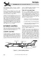
The anticollision light system consists of two
dual selectable beacon/strobe light units. The
upper anticollision light is located on the top
of the vertical stabilizer, and the lower light
is mounted on the bottom of the wing/fuselage
fairing (Figures 3-13, 3-18 and 3-19).
Each anticollision light assembly contains
two flash tubes, one with an aviation red fil-
ter (beacon) and one with a clear filter (strobe).
On unmodified aircraft the three position
switch is labeled BCN/STROBE – BCN – OFF.
On aircraft modified by SB 45-33-2 the three
position switch is labeled STROBE – BCN –
OFF. When BCN/STROBE is selected on un-
modified aircraft only the red flash tube in
each light flashes when the aircraft is on the
ground (via squat switch ground mode sig-
nal) and the clear flash tube is inhibited until
airborne. Anytime the BCN position is se-
lected the red flash tube flashes. On aircraft
modified by SB 45-33-2, the white flash tube
in each light flashes when STROBE is se-
lected and the red flash tube flashes when the
BCN position is selected; there is no auto-
matic control through the squat switch. If
flight into weather is encountered and the
strobe light becomes disorienting, the switch
can be set to either BCN or OFF.
The combined anticollision light system has
a flash rate of approximately 100 pulses per
minute. The system receives power from the
l e f t m a i n b u s a n d i s p r o t e c t e d b y t h e
“ B C N / S T RO B E ” c i r c u i t b r e a ke r l o c a t e d
within the LIGHTS group on the pilot circuit
breaker panel.
L E A R J E T 4 5
P I L O T T R A I N I N G M A N U A L
3-14
FOR TRAINING PURPOSES ONLY
FlightSafety
international
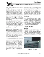
Figure 3-16. Wing-Tip Navigation Light
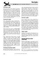
Figure 3-18. Upper Anticollision Light
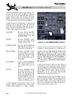
Figure 3-17. Tail Navigation Light
Figure 3-19. Lower Anticollision Light