


indication turns amber. Spoileron operation
will not cause the “SPOILER EXT” message
to illuminate.
Flaps Electrical Power
Electrical power for flap operation is from
the left and right essential busses. The R FLAP
POS and the FLAP CTRL circuit breakers are
located in the FLIGHT group on the copilot’s
circuit breaker panel and the L FLAP POS
circuit breaker is located in the FLIGHT group
on the pilot’s circuit breaker panel.
SPOILERS
General
The spoilers are located on the upper surface
of the wings forward of the flaps. Each spoiler
is hinged at three points and is extended/re-
tracted with a single hydraulic actuator. They
may be extended symmetrically for use as
speed brakes or asymmetrically for aileron
augmentation (spoileron mode).
In the Learjet 45, spoileron operation is full
time. Anytime either control wheel is turned
more than 5°, there is a differential displace-
ment of the spoiler surfaces to augment roll
control. An autospoiler system is installed to
automatically extend both spoilers to spoil
lift after landing or during an aborted takeoff.
If the ailerons become jammed, the pilot’s
control wheel can be disconnected from the
aileron system and used to operate spoilerons
for roll control.
The spoilers are electrically controlled through
a lever on the top, left side of the throttle quad-
rant and a spoileron controller (computer) lo-
cated on the aft pressure bulkhead (Figure
15-21). The aileron disconnect lever on the
pilot’s control wheel is used to disconnect the
control wheel from the ailerons and signal the
spoileron controller to activate the roll dis-
connect mode of operation.
Spoiler Lever
The spoiler position lever is located on the
throttle quadrant and is linked to two RVDTs
(rotary variable differential transformers).
There are three labeled settings for the spoiler
lever that correspond to detent positions: RET
(retract), ARM (autospoilers), and EXT (full
extension - approximately 60° at slower air-
speeds) (Figure 15-22). The range between
the ARM and EXT detents allows for variable
spoiler positions inflight. There are also two
unmarked detent positions between ARM and
EXT which correspond to intermediate spoiler
extension positions of approximately 15° and
30°.
Spoiler Indications
Spoiler extension is indicated on the SUMRY
page and on the FLT system schematic page
(Figure 15-21). Either of these two pages can
be displayed at the bottom of the EICAS or at
the bottom of the MFD.
On the SUMRY page, spoiler (SPLR) exten-
sion is a digital indication under the “FLT” col-
umn on the right side of the page. On the FLT
system schematic display, spoiler extension is
presented as a digital display and as a verti-
cal analog scale with dual pointers - one for
each spoiler.
15-25
FOR TRAINING PURPOSES ONLY
L E A R J E T 4 5
P I L O T T R A I N I N G M A N U A L
FlightSafety
international
20
10
10
160
180
1
0
9
160
FMS
AP
120
100
14
RF
M
A
X
S
P
D
25
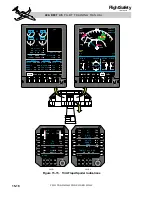
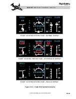
MA
LOW AIRSPEED
AWARENESS
INDICATION
(RED)
OVERSPEED
INDICATOR
(RED)
Figure 15-20. PFD – Airspeed Indications