


dual, redundant mechanical cable system,
push/pull tubes, sectors, and bellcranks.
Scuppers are provided on the bottom side of
each elevator for moisture drainage and three
static discharge wicks are attached to the trail-
ing edge of each elevator.
The elevator system uses two separate cable
runs (Figure 15-2). The pilot's control col-
umn is tied through one cable circuit to the left
hand elevator and the copilot's control col-
umn is tied through another cable circuit to the
right elevator. The pilot’s control cables run
on the bottom of the airplane and the copilot’s
run on the top for separation in the rotor burst
area.
Normally, the two control circuits are con-
nected and the control columns and elevators
operate in unison. However, in the event of a
jammed elevator (either control circuit), the
two sides can be disconnected and flight can
be continued with the unjammed control col-
umn and elevator.
Autopilot Pitch Servo
Autopilot elevator operation is provided by the
autopilot pitch servo actuator that is con-
nected to the elevator aft sector assembly
(Figure 15-2).
The pitch servo actuator is a two direction
torque motor. It incorporates an electrical
clutch that engages only when the autopilot is
engaged. If a system malfunction causes the
servo to produce an undesired elevator move-
ment, the crew can disengage the servo by
disengaging the autopilot or by depressing ei-
ther control wheel master switch (MSW).
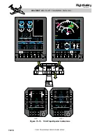
Depressing and holding the touch control
steering (TCS) button will also disengage the
clutch while held, but does not disengage the
autopilot (Figure 15-3).
The pitch servo receives electrical power
through the AFCS SERVOS circuit breaker
located in the FLIGHT group on the pilot's cir-
cuit breaker panel.
Elevator Up/Down Spring
The elevator up/down spring assembly is in-
terconnected between the elevator upper and
lower pushrods in the vertical stabilizer (Figure
15-2). Additional pushrods, attached to the
bottom of the horizontal stabilizer toward the
leading edge, connect to the up/down spring
assembly (Figure 15-13). When the horizon-
tal stabilizer is moved up or down for pitch
trim, the pushrods affect the up/down spring
tension which is applied to the elevator
pushrods. The up/down spring assembly aug-
ments pitch stability at cruise speeds by pro-
viding higher elevator stick force per increment
change in air velocity, and provides additional
nose up trim at low speeds.
Pitch Trim Bias
The pitch trim bias system works in conjunc-
tion with the up/down spring assembly. Its
function is to assist the pilot by providing ad-
ditional spring pressure (bias) against the el-
evator air loads in the event the horizontal
stabilizer is jammed in an out-of-trim position.
An electrical linear actuator is connected
through a spring to the aft elevator sector in a
position which allows it to increase pressure
15-4
FOR TRAINING PURPOSES ONLY
L E A R J E T 4 5
P I L O T T R A I N I N G M A N U A L
FlightSafety
international
IDENT SWITCH
(NOT SHOWN)
ARMING
BUTTON
AP PITCH/ROLL
COMMAND SWITCH
CONTROL WHEEL
TRIM SWITCH
(CWTS)
MIC
SWITCH
(NOT SHOWN)
CONTROL WHEEL
MASTER SWITCH (MSW)
CHECKLIST
LINE ADVANCE
TOUCH
CONTROL
STEERING
(TCS)
Figure 15-3. Pilot’s Control Wheel