DISTRIBUTION
GENERAL
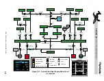
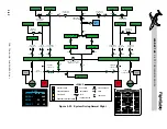
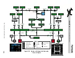
The basic DC power distribution is illustrated
in Figure 2-17. Power from the left and right
batteries, through two 40 amp fuses, is always
available to the “hot wired” items connected
to the rear hot bus, the left and right hot busses,
and the left and right emergency hot busses
even when the main battery switches are off.
Battery power to the left and right hot busses
also passes through a single 40 amp fuse and
15 amp circuit breakers for each bus.
The left and right fire extinguishers and the
left and right FWSOVs (fire-wall shutoff
valves) receive power through the left and
right emergency hot busses respectively. These
items can also receive power from the emer-
gency battery, either main engine generator,
external power source or APU if installed
(Figure 2-17). The tailcone utility light, sin-
gle-point refueling (SPPR) and baggage com-
partment lights are powered through the rear
hot bus. Additional hot bus items include the
left cockpit overhead light and entry lights
(Table 2-4). The hot busses are connected di-
rectly to both of the main batteries and to the
external power connector through the left
generator bus.
Power to the radio control hot bus is controlled
with a switch on the center pedestal. The radio
control hot bus can only be selected ON when
the airplane batteries are OFF. If the radio
control hot bus is selected ON and the batter-
ies are subsequently selected ON, the radio
control hot bus will automatically be turned
off and the ON annunciator on the switch will
extinguish. The switch is labeled “RADIO
CONTROL HOT BUS.” When this switch is
depressed, the ON annunciator on the switch
will illuminate and main battery power through
the right forward hot bus will power the fol-
lowing (normal power source shown in paren-
thesis):
• Left & right audio control unit (L & R
ESS)
• Clearance delivery head (L ESS)
• COMM section of the integrated com-
munication unit #1(L ESS)
• NAV section of the integrated naviga-
tion unit #1 (L ESS)
With ground power connected, the bus-tie will
automatically close and the output of the GPU
is applied to the left and right generator busses
and non-essential busses. With the main and
emergency batteries selected on, external power
is distributed to the rest of the DC electrical sys-
tem. The airplane batteries (main and emer-
gency) will then be charged from the power
supplied by the GPU.
The APU (if installed) can supply power to
the electrical system through the right gener-
ator bus. When the APU generator is on-line,
the bus-tie will automatically close if the left
generator is not on-line, providing power to the
left generator bus as well. Electrical power is
then distributed from the generator busses to
the rest of the electrical system in the same way
as if a GPU was providing electrical power
with airplane batteries selected ON.
The APU generator output voltage can be mon-
itored on the EICAS in the same manner that
GPU or airplane generator voltage is moni-
tored. Additionally, APU amperage draw can
be monitored on an indicator located on the
APU control panel on the center pedestal or on
the ELEC schematic page of the EICAS/MFD.
L E A R J E T 4 5
P I L O T T R A I N I N G M A N U A L
2-23
FOR TRAINING PURPOSES ONLY
FlightSafety
international


