


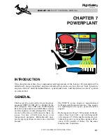


MAJOR SECTIONS
For descriptive purposes, the engine (Figure
7-1) is divided into seven major sections as
follows:
1. Air Inlet
2. Fan
3. Compressor
4. Combustor
5. Turbine
6. Exhaust
7. Accessory
AIR INLET SECTION
The main air inlet is formed by the nacelle inlet
duct. Engine nacelle installation consists of an
acoustically treated inlet and a single skin riv-
eted and spot welded aluminum alloy con-
structed inlet assembly. The simplicity of
design eliminates the need for aerodynamic
guide vanes and variable geometry, minimiz-
ing inlet icing and reducing noise and weight.
Each engine nacelle inlet is anti-iced by in-
dividually controlled engine bleed air. A tem-
perature and pressure sensor within the inlet
is electrically heated.
FAN SECTION
The fan section consists of a single-stage fan
rotor assembly, a fan support assembly, the by-
pass stator, the inlet housing and the planetary
gear assembly. See Figure 7-1.
Functionally, the fan section accelerates a
high airflow into the full-length bypass duct
and to the high-pressure compressor section.
The fan generated airflow passing through
the bypass duct contributes the major portion
of the total thrust at lower altitudes. This by-
pass propulsive force decreases as altitude
increases.
Powered by the low pressure turbine, the plan-
etary gear reduction assembly provides power
to drive the titanium fan assembly. The rpm of
the low pressure rotor is designated “N1”
(commonly referred to as “fan speed”). Engine
thrust is set using this rpm indication.
The unheated spinner is bolted to the front of
the fan. The fixed-in-place stator directs the
majority of the airflow into the bypass duct,
and the remainder into the compressor inlet
duct. The fan inlet housing is cast titanium and
provides a sound-attenuated inlet duct which
also incorporates a ring of armor plate for fan
blade containment. The digital electronic en-
gine control (DEEC) unit is mounted to the ex-
terior upper area of the housing unit.
COMPRESSOR SECTION
The compressor area consists of the low pres-
sure (LP) and high pressure (HP) compressor
sections (Figure 7-2). The LP is a four stage
axial flow compressor housed within the LP
case assembly.
The LP compressor is comprised of four ro-
tating compressor discs (rotors) and four non-
rotating stator rings. Each compressor rotor is
surrounded by a shroud. Each stator ring con-
tains vanes which form a divergent duct al-
lowing air pressure to increase and serve to
direct airflow at the optimum angle to the suc-
ceeding wheel. As airflow progresses through
L E A R J E T 4 5
P I L O T T R A I N I N G M A N U A L
7-2
FOR TRAINING PURPOSES ONLY
FlightSafety
international