


r u d d e r p e d a l f o r c e r e a c h e s 2 5 p o u n d s .
Additionally, in flight the flaps must be ex-
tended to greater than 3° and airspeed must be
less than approximately 180 knots for rudder
boost to function.
The rudder boost will override the yaw damper
(if engaged) when the rudder pedal force
threshold is reached. When the force on the
rudder pedals is released, the yaw damper will
resume operation.
The #2 IC-600 computer provides all compu-
tational aspects for the rudder boost and yaw
damper systems. Two dual-redundant force
sensors are installed on the rudder pedal as-
sembly. Both outputs of each sensor provide
rudder force data to the #2 IC-600. Outputs
from the force sensors are also used by the
nosewheel steering system.
The rudder boost system is armed when the
RUDDER BOOST switch, located at the front
of the center pedestal (Figure 15-10) is se-
lected to ON. When the RUDDER BOOST
switch is ON, the S/I is dark and when it is not
on, "OFF" will be illuminated in the S/I. A
white "RUD BOOST INOP" message is posted
on the CAS when the switch is OFF.
An amber “RUD BOOST INOP” is posted on
the CAS if the rudder boost is inoperative
and the switch is not selected OFF. Depressing
and holding either Control Wheel Master
Switch (MSW) will also disable rudder boost
and generate an amber “RUD BOOST INOP”
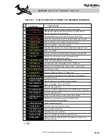
CAS (Table 15-1).
SECONDARY FLIGHT
CONTROLS
HORIZONTAL STABILIZER
The moveable horizontal stabilizer is attached
to the vertical stabilizer at forward and aft at-
tachment points. The aft attach point is the
pivot, which consists of a large hinge pin in-
serted through bearings located in the hori-
zontal and vertical stabilizer. The forward
attach point is connected to the horizontal sta-
bilizer actuator which is attached to the ver-
tical stabilizer forward spar. The position of
the horizontal stabilizer is controlled through
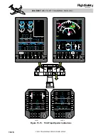
t h e p r i m a r y a n d s e c o n d a r y t r i m s y s t e m s
(Figure 15-13).
TRIM SYSTEMS
General
The ailerons and rudder are trimmed with con-
ventional tabs on the control surfaces.
The pitch trim system relieves control col-
umn (elevator) loads by moving the horizon-
tal stabilizer. A dual-motor (primary and
secondary), screwjack-type pitch trim actu-
ator moves the leading edge of the horizontal
stabilizer up or down in response to pitch trim
inputs. The primary motor is actuated by man-
ual primary pitch trim (crew actuated), con-
figuration trim, and Mach trim systems. The
secondary motor is provided as a back-up for
primary trim and is operated by the airplane
secondary pitch trim (crew actuated) and the
autopilot (Figure 15-13).
A trim-in-motion system is incorporated with
the trim system, but only functions when the
autopilot is engaged.
Each section of the pitch trim actuator (primary
and secondary) provides position sensor in-
formation to the IC-600s for pitch trim indi-
cation displays.
A three position, lever-lock, trim selector
switch is located on the center pedestal to
15-12
FOR TRAINING PURPOSES ONLY
L E A R J E T 4 5 P I L O T T R A I N I N G M A N U A L
FlightSafety
international