


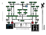


fed by the left and right generator busses re-
spectively through 150 amp fuses, essential
bus contactors and 80 amp circuit breakers. The
left and right essential bus contactors auto-
matically close when the respective left and
right main battery switches are turned on and
automatically open during starter operation.
The essential busses are tied by a left and right
isolation contactor so that they are both pow-
ered by the emergency battery during engine
start and they will be powered by either gen-
erator bus if an essential bus contactor should
fail in flight.
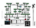
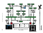
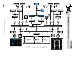
ISOLATION CONTACTORS
There are two isolation contactors located
within the electrical system (Figure 2-17).
The right isolation contactor is located be-
tween the R Essential Contactor and the EMER
BATT BUS, and the left isolation contactor is
located between the L Essential Contactor and
the EMER BATT BUS. The isolation contac-
tors are automatically controlled and there
are no provisions to manually over-ride the op-
eration.
Except during starter-assisted engine start,
the left isolation contactor is normally open
and the right isolation contactor is normally
closed. With the right isolation contactor
closed, the right generator bus powers the
emergency battery bus and charges the emer-
gency battery.
During ground start and for starter-assisted
airstart, the isolation contactors close and the
left and right essential contactors automati-
cally open. This allows the emergency bat-
tery to power the emergency battery bus,
essential busses, and essential avionics busses
and isolate these busses from voltage fluctu-
ations caused by starter operation. After starter
drop-out, the left isolation contactor opens
and the essential contactors close.
There are two abnormal conditions that will
cause the left isolation contactor to automat-
ically close. If either essential contactor fails
(opens), the left isolation contactor will close.
Since the right isolation contactor is normally
closed, either generator bus can then provide
generator power through the essential con-
tactor that is closed to the left and right es-
sential busses and to essential avionics busses,
the emergency battery bus and to charge the
emergency battery. This failure will be dis-
played as a “L/R ESS BUS FAULT” message
on the CAS.
The “L or R ESS BUS FAULT” CAS message
will be amber if the respective essential bus
contactor has failed open while on the ground.
While in flight, the CAS message will be
white.
The left isolation contactor will also close in
the event that the right isolation contactor
fails (open). This will allow the emergency bat-
tery bus and emergency battery to receive
power from the left generator bus. There is no
indication of this condition to alert the crew.
ESSENTIAL AVIONICS BUSSES
The left and right essential avionics busses are
powered from the left and right generator
busses respectively through the L/R essential
contactor and L/R essential avionics contac-
tor. In addition to the 150 amp fuses protect-
ing the essential bus feeders, the essential
avionics busses are also protected with 35
amp circuit breakers. Under normal condi-
tions, the essential contactors will automati-
cally be closed, providing power to the
essential avionics contactors. The essential
and main avionics contactors are closed and
opened by manual selection of the left and
right avionics master switches. These essen-
tial avionics busses, like the essential busses,
are powered by the emergency battery during
starter-assisted airstart while the main avion-
ics busses are depowered.
L E A R J E T 4 5
P I L O T T R A I N I N G M A N U A L
2-25
FOR TRAINING PURPOSES ONLY
FlightSafety
international