
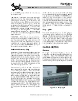


Entry/Exit Light
The cabin entry/exit door light is installed in
the upper main door to provide illumination
of the lower door steps when both doors are
open. This light is controlled by the ENTRY
light switch (Figure 3-7) and is powered by the
right hot bus regardless of the battery switch
position. The light is inoperative when the
entry door is closed. The entry/exit light is pro-
tected by a circuit breaker labeled “ENTRY,”
located within the CABIN light group on the
copilot circuit breaker panel.
Overhead Lights
The overhead lights consist of indirect fluo-
rescent lighting located within the cabin cen-
ter headliner. The cabin overhead lights can
be turned ON/OFF with the CABIN LIGHT
switch on the main entry door control panel
(Figure 3-7) or with the CABIN LIGHT switch
in the cockpit, or through the MASTER CON-
TROL PANEL.
When using the entryway CABIN LIGHT
switch, the cabin lights come on full bright.
They may be dimmed by depressing and hold-
ing the switch for a short duration. Depressing
and holding the switch a second time will
brighten the cabin lights and depressing and
quickly releasing the switch turns the lights
OFF.
The cockpit switch takes priority over the
other cabin lights controls. The CABIN
LIGHT switch turns the cabin lights on or off
from the cockpit. If the switch is held de-
pressed for several seconds, the cabin lights
begin to flash. The CABIN LIGHTS and SPOT
LIGHTS can be disabled with the DISABLE
CABIN switch in the cockpit. The cabin over-
head lights are powered by the left main bus
and are protected by the “CABIN” circuit
breaker within the CABIN group on the pilot
circuit breaker panel.
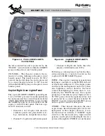
Passenger Reading Lights
Reading and table lighting consists of 16 eye-
ball-type directional lights installed above the
seats on each side of the cabin. Some seats have
only one light, while others consist of a two-
light assembly, referred to as table lights.
Control for the reading lights is by the seat
mounted control units (Figure 3-7) or by the
SPOT light switch on the main entryway con-
trol panel. Power for the reading lights is pro-
vided by the right non-essential bus and they
are protected by the “L and R SPOT” circuit
breakers located within the CABIN group on
the pilot and copilot circuit breaker panels.
Lavatory Lights
Lavatory lights consist of two overhead spot-
lights, overhead fluorescent lights and a van-
ity light (optional). Control of the spotlights
is by the lavatory control panel and the main
entryway control panel. The fluorescent light
is controlled by the LAV LIGHT switch on
the main entryway control panel or the LAV
LIGHT switch on the lavatory control panel.
The lavatory lights are powered by the left
and right non-essential bus and protected by
the “LAV and R & L SPOT” circuit breakers
within the CABIN group on the pilot and copi-
lot circuit breaker panels.
Galley Lights
Lighting for the passenger refreshment area is
powered by the right non-essential bus and
protected by the “GALLEY” circuit breaker
within the CABIN group on the copilot circuit
breaker panel.
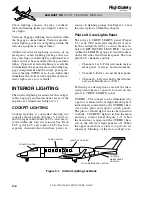
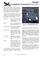
BAGGAGE/TAILCONE
LIGHTING
Lighting for the baggage compartment consists
of two overhead dome lights. The lights are
controlled by the BAGGAGE LIGHTS switch
located on the ceiling of the baggage com-
partment (Figure 3-8). The baggage com-
partment lights are powered by the airplane hot
bus system, and if they are inadvertently left
on, will automatically extinguish when the
baggage door is closed.
The tailcone equipment bay internal light is
also powered by the hot bus system. The
L E A R J E T 4 5
P I L O T T R A I N I N G M A N U A L
3-8
FOR TRAINING PURPOSES ONLY
FlightSafety
international