STALL WARNING SYSTEM
GENERAL
The stall warning system, also referred to as
the angle of attack (AOA) system, is installed
to provide the crew with an indication of im-
pending airplane stall. The system is actually
two independent systems that use a dual chan-
nel computer.
Other system components include two AOA
sensors, control column shaker motors and an
interface with the PFDs through the IC-600s.
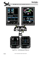
Left and right AOA indicators are available as
an option (Figure 15-23).
Each channel of the computer generates a ref-
erence signal to the corresponding stall vane
and, in return, receives AOA information. The
computer then processes this information with
airspeed, altitude, flap setting, and weight-
on-wheels inputs to determine the stall warn-
ing indications.
STALL WARNING INDICATIONS
The stall warning computer sums inputs of
AOA and altitude along with flap position
from the flap position indication unit. Stall
warning is biased for each flap setting and al-
titude based upon ADC reported altitude in-
formation.
The stall warning system provides the fol-
lowing aural, tactile, and visual indications
when the predetermined conditions have been
reached (Figure 15-23):
• The left and right channels of the com-
puter drive the low speed awareness
(LSA) indication. The LSA cue is a ver-
tical red bar on the inside of the air-
speed tape which rises from the bottom
as the airplane AOA increases. The point
at which the red bar reaches the air-
speed pointer will coincide with the
point at which other stall warning in-
dications are activated.
• The left and right channels of the stall
computer will activate the control col-
umn shaker motors.
• The non-cancellable voice message
“STALL” will repeat until the AOA is
decreased.
• The AOA indicators (if installed) will
enter the the red band on the indicator.
STALL WARNING OPERATION
The stall warning system does not have on-off
switches. If the circuit breakers are in, the
systems are powered when the airplane elec-
trical system is powered up. If installed, the
AOA indicators will operate on the ground, but
the shakers and other visual and aural stall
indications are inhibited until the airplane has
been airborne approximately 5 seconds (except
during stall test).
The stall warning system preforms a power-
up self-test (BITE) and monitors for a num-
ber of possible system faults. Detection of a
fault causes an amber “L or R STALLWARN
FAIL” message to appear on the CAS.
Anti-icing of the AOA vanes is also moni-
tored by the stall system. If the L and R
PROBES S/Is are on and power is not avail-
able to both AOA vanes for heating, an amber
“L or R AOA HT FAIL” message appears on
the CAS.
If angle of attack information to the IC-600 be-
comes invalid, an amber AOA will be dis-
played at the bottom right side of the airspeed
scale and the LSA cue will not be present. See
example in Figure 15-23. This would also be
accompanied by an amber “L or R STALL-
WARN FAIL” message on the CAS.
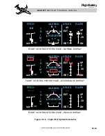
On the system test knob a STALL test po-
sition is provided for testing the stall sys-
t e m s b e f o r e t a k e o ff . W h e n t h e S TA L L
position is selected and the test button is de-
pressed and held, the stall test sequence is
initiated. While the System Test switch is de-
pressed, both PFD’s will have a red “ADC
TEST” annunciated in the upper left corner.
15-31
FOR TRAINING PURPOSES ONLY
L E A R J E T 4 5
P I L O T T R A I N I N G M A N U A L
FlightSafety
international


