


EMERGENCY BATTERY BUS
The emergency battery bus (Figure 2-17) is
normally powered from the right generator bus
through the right essential contactor and right
isolation contactor, but for engine starting and
in the event of dual generator failure, it is
powered directly from the emergency battery.
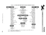
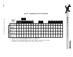
See Table 2-4 for a list of equipment powered
by the emergency battery bus.
In the event of a dual generator failure, the right
isolation contactor opens (left one normally
already open), leaving the main aircraft bat-
teries to power the respective essential busses
and the emergency battery to power the emer-
gency battery bus. Hence, three independent
battery channels are operating following a
dual generator failure. The 10 ampere hour
emergency battery should power the emer-
gency battery bus for at least one hour after
being isolated from the rest of the electrical
system.
NON-ESSENTIAL BUSSES
The left and right non-essential busses, nor-
mally connected to the respective generator
busses, are used to supply non-critical loads,
including certain cabin lighting and domestic
loads. When the aircraft electrical system is
powered only with airplane batteries, the non-
essential busses are not powered and the OFF
captions will be illuminated on both NON-
ESS switches. If a GPU or APU is selected ON,
but the main batteries are OFF, only the non-
essential busses are powered. When a GPU,
APU, or airplane generator is powering the
electrical system, and the main batteries are
ON, the non-essential bus contactors will au-
tomatically close and the OFF captions will ex-
tinguish if the aircraft is on the ground.
However, if either generator fails in flight,
the non-essential busses are both automati-
cally disconnected to reduce the electrical
load. After reducing the electrical load in ac-
cordance with AFM procedures, one or both
non-essential busses may be subsequently re-
c o n n e c t e d b y d e p r e s s i n g t h e N O N - E S S
switches on the electrical control panel.
DISTRIBUTION SUMMARY
The following series of illustrations show the
DC power flow and bus status during a typi-
cal sequence of events.
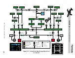
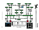
Figure 2-18 illustrates the current flow with
only main and emergency battery power on and
avionics master switches OFF. In this situation
the non-essential busses are not powered and
cannot be selected on to prevent inadvertent
battery depletion.
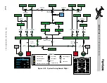
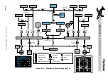
Figure 2-19 illustrates the current flow through
the electrical system with external power
(GPU) connected and main batteries, and the
emergency battery selected on. The bus-tie
connecting the two generator busses is auto-
matically closed. The illustration also shows
the avionics master switches selected to on
which closes the contactors to the left and
right essential avionics busses and the left and
right main avionics busses. Note that the
EMER BATT switch caption (“EMER”) is no
longer illuminated as this battery is no longer
discharging. The same conditions would exist
with a APU powering the electrical system
except the contactor between the GPU and the
left generator bus would be open and the APU
contactor would be closed.
Figure 2-20 illustrates the electrical system sta-
tus during an engine start using airplane bat-
teries. The essential busses and emergency
battery bus have been isolated and are powered
from the emergency battery during engine
start. The non-essential busses and main avion-
ics busses are also automatically depowered
for engine start. In this illustration the avion-
ics master switches are turned off for engine
start, but if they had not been, the L & R main
avionics busses would have been automati-
cally depowered during start.
L E A R J E T 4 5
P I L O T T R A I N I N G M A N U A L
2-26
FOR TRAINING PURPOSES ONLY
FlightSafety
international