The secondary trim actuator also monitors for
uncommanded trim, trim in wrong direction
and incorrect trim rate. If any of these mal-
functions are detected, an amber “SEC TRIM
FAIL” CAS message is posted and the sec-
ondary actuator is disabled. The IC-600s have
no control or monitor functions for manual
secondary trim.
Autopilot Pitch Trim
The #2 IC-600 houses the control and moni-
tor circuits for autopilot operation. When the
autopilot is engaged, it controls the airplane
pitch attitude using the pitch servo and the
secondary pitch trim actuator. During autopilot
operation, the secondary trim actuator con-
tinues to monitor for uncommanded trim and
trim direction; additionally, the #2 IC-600
monitors for uncommanded trim, trim direc-
tion and incorrect trim rate. If the actuator
detects one of the above faults, an amber “SEC
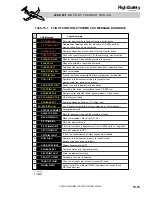
TRIM FAIL” CAS message is posted (Table
15-1).
Trim-In-Motion Indication
A trim-in-motion RVDT is installed on the
secondary trim actuator. When the autopilot
energizes the secondary trim actuator for more
than 2 to 3 seconds, a series of audible clacker
sounds is transmitted through the audio sys-
tem. A built-in time delay allows trim opera-
tion for approximately 2 to 3 seconds before
the clacker sounds to prevent nuisance actu-
ation on the clacker.
There is no trim-in-motion clacker for any
trim operation other than autopilot trim.
Secondary Trim Electrical Power
Electrical power for the secondary pitch trim
system is provided by the R Essential Bus.
The circuit is protected by the TRIM - SEC
PITCH circuit breaker located in the FLIGHT
group on the copilot’s circuit breaker panel.
Trim Indications
Pitch, aileron, and rudder trim indications are
provided on the EICAS and the MFD. A dig-
ital display of pitch trim position (PIT TRIM)
is always in view below the CAS window, on
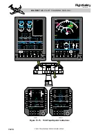
the right side of the EICAS (Figure 15-15).
Pitch (PIT), aileron (AIL), and rudder (RUD)
trim are all digitally displayed on the SUMRY
page. They are arranged in a vertical column
labeled “FLT” on the right side of the SUMRY
page (Figure 15-15). The SUMRY page is the
power-up default display on the EICAS and
should always be in view for takeoff and land-
ing. The SUMRY page can also be displayed
at the bottom of the MFD.
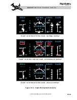
Trim indications are also displayed on the
FLT system schematic page, which can be
called up for display at the bottom of the
EICAS or MFD. Pitch, aileron, and rudder
trim are displayed on the FLT page in a digi-
tal format and also in an analog scale and
pointer format (Figures 15-15 and 15-16).
Pitch trim is displayed on the left side of the
FLT system schematic page. The pitch trim
scale is from 0 (full nose down) to 10 (full nose
up). The analog pitch trim indicator scale is
vertical with nosedown (NDN) at the top and
noseup (NUP) at the bottom. The analog scale
has a white takeoff band on it between 5.3
units and 8.7 units.
An analog aileron trim scale and rudder trim
scale are located in the center of the FLT sys-
tem schematic page. They each have a digital
readout of the respective trim settings above
the analog scales.
Aileron and rudder trim increments are both
0 to 10 units L (left wing down or left rudder)
and R (right wing down or right rudder). A
white takeoff trim band is located on both
scales between 1 unit left and 1 unit right.
Trim tab position information is provided
through tab position transmitters (poten-
tiometer) located on the tab actuator motors.
The trim setting for pitch, aileron, and rudder
15-20
FOR TRAINING PURPOSES ONLY
L E A R J E T 4 5 P I L O T T R A I N I N G M A N U A L
FlightSafety
international


