


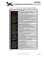


Flap Monitor System
The flap control unit performs a self-test at
power up and monitors for faults/failures
within the system at all times. The AFM re-
quires the crew to perform a flap preflight test
using the system test knob.
The FLAPS position on the test knob is used
during preflight to check the asymmetry mon-
itors, the uncommanded movement monitor
and to verify the shutdown circuits (Figure
15-19). A satisfactory test is indicated by il-
lumination of the amber “FLAPS FAIL” and
“FLAPS FAULT” messages on the CAS.
If a fault is detected, an amber “FLAPS
FAULT” message is posted on the CAS (Table
15-1). The flaps should still be operational in
this case, but may operate in a degraded mode.
The fault may be resettable if the fault condi-
tion clears. Anytime the flap selector and flap
position do not agree, the “FLAPS FAULT”
CAS message appears and the flap position in-
d i c a t i o n i s b o x e d a n d t u r n s t o a m b e r.
Positioning the flap selector to agree with flap
position may clear the fault message.
If a failure occurs within the flap system, an
amber “FLAPS FAIL” message will be posted
on the CAS and the system will be inoperative.
With a failure, power will be shut-off to the
arming solenoid valve and all extend/retract
commands to the flap power unit will be dis-
abled.
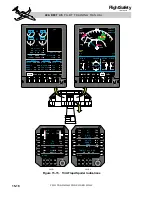
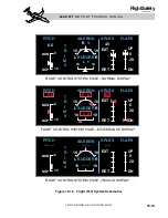
One malfunction that will cause a FLAPS
FAIL message is flap asymmetry. If the flap
control unit detects flaps split by more than 2°
to 7°, depending on flap speed, a “FLAPS
FAIL” message is generated and the flap po-
sition pointers on the FLT system schematic
turn red. The asymmetry can be verified on the
FLT system schematic page. Another mal-
function that will cause a FLAPS FAIL mes-
sage is uncommanded movement of the flaps.
The crew cannot reset the flap system after ex-
periencing flap asymmetry or uncommanded
movement malfunctions. However, it may be
possible to reset the system after other mal-
functions using the FLAP RESET position on
the system test knob (Figure 15-19).
Flap Operation
The flaps can be set to 8° or 20° for takeoff;
if they are not, the takeoff configuration mon-
itor and indicating system will bring it to the
crews attention.
Flap speed limits (V
FE
) are: 250 KIAS - flaps
8°, 200 KIAS - flaps 20°, and 150 KIAS -
flaps DN (40°). These speeds are placarded
next to the flap selector lever (Figure 15-18).
The overspeed indicator on the PFD airspeed
scale automatically adjusts to indicate the
maximum speed for the flap setting and the
overspeed indications occurs if flap speeds
are exceeded (Figure 15-20).
The configuration trim circuitry in the #1 IC-
600 will normally provide automatic pitch
trim compensation whenever the position of
the flaps is changed. This function will not be
available in bypass trim or anytime the #1 IC-
600 is not functional.
As a backup to the normal gear warning sys-
tem, gear warnings occur if flaps are set below
25° and any gear is not down and locked.
Flaps and spoilers must not be extended at the
same time. If the flaps are extended to more
than 3° and the spoilers are extended any
amount, the amber “SPOILER EXT” message
is posted on the CAS and the spoiler position
15-24
FOR TRAINING PURPOSES ONLY
L E A R J E T 4 5
P I L O T T R A I N I N G M A N U A L
FlightSafety
international
SYS TEST/RESET
FLAP
RESET
ANTI
-ICE
SPLRN
RESET
STALL
GPWS
ADC
FLAPS
GEAR
LTS
FIRE
DET
OFF
PR
E
S
ST
E
S
T
Figure 15-19. System Test Knob