


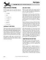

Turbine
A single-stage turbine is rigidly mounted on
the compressor rotor shaft. The turbine is de-
signed to extract energy from the expanding
combustion gases to drive the compressor and
t h e a c c e s s o r y g e a r b o x . E x h a u s t G a s
Temperature (EGT) information from a ther-
mocouple located in the turbine exhaust noz-
zle is provided to the ECU for engine control
and monitoring.
Exhaust
The exhaust section consists of an exhaust
pipe extending into an exhaust ejector. The ex-
haust ejector is designed to pull inlet air across
the APU for cooling of the starter/generator
and other components within the containment
box. The rectangular exhaust outlet is located
on the upper right side of the rear fuselage, just
aft of the Air Cycle Machine (ACM) exhaust,
above the right engine pylon (Figure 6-4).
Accessory Gearbox
The accessory gearbox, driven by the power
section, reduces the high speed, low torque
power section rpm to the low speed, high
torque required to drive the DC starter/gen-
erator. The accessories include the lubricating
pump assembly, fuel control and fuel pump
unit, and the starter/generator.
APU COOLING FANS
Due to potentially high tailcone temperatures
when the APU is operating, cooling fans and
vents are installed in the aft equipment bay.
One fan/vent assembly is installed on the left
side of the aft equipment bay just aft of the bag-
gage door (Figure 6-5). The other fan/vent as-
sembly is installed in the tailcone door (Figure
6-6).
In the event of a fault in the cooling fan sys-
tem, an amber magnetic indicator illuminates.
The indicator, along with a reset switch, is
6-4
FOR TRAINING PURPOSES ONLY
L E A R J E T 4 5
P I L O T T R A I N I N G M A N U A L
FlightSafety
international
Figure 6-4. APU Exhaust Outlet
Figure 6-5. Left Side APU Cooling Fan
Figure 6-6. Right Side APU Cooling Fan