


in the CABIN group of circuit breakers on
the copilot side.
PEDESTAL – This rheostat controls the light-
ing intensity for the center pedestal. The
FMS display intensity is regulated by the
d i m b u t t o n o n t h e F M S c o n t r o l p a n e l .
Pedestal lighting receives power from the
right main bus and is protected by a circuit
breaker labeled “PEDESTAL” located within
the LIGHTS group on the copilot circuit
breaker panel. The brightness of the GEN
AMPS display on the APU control panel (if
installed) is controlled by the pilot’s INSTR
lights rheostat.
CB PANEL – This rheostat controls the in-
tensity of overlay lighting to the copilot’s cir-
cuit breaker panel. The panel receives 28
VDC power from the right main bus and is
protected by a circuit breaker labeled “R
CB” located within the LIGHTS group on
the copilot circuit breaker panel.
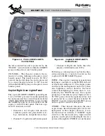
Switch/Indicators (S/Is)
A majority of the switches in the cockpit are
of the pushbutton switch/indicator (S/I) type.
They are designed so that none of the S/Is are
illuminated under normal conditions, which
supports the “dark cockpit” concept. For ex-
ample, the generator S/Is on the electrical
control panel are black (blank) when the gen-
erators are ON and “OFF” illuminates in the
S/Is when the generators are off.
For redundancy, each of the S/Is contain four
bulbs and receive power from two different
sources. The pilot lighting control unit (LCU)
supplies power to the two left bulbs and the
copilot’s LCU supplies power to the right two
bulbs in most of the S/Is. Exceptions to this
are the RAD HOT BUS S/I, which receives
power from the hot bus, and the warning S/Is
(MASTER WARN/CAUT and engine FIRE
PUSH) which receive power through the crew
warning panel (CWP). The S/I legends illu-
minate full bright when the NAV lights are
OFF and are step dimmed with NAV lights
ON.
A S/I bulb test may be initiated by selecting
LTS on the system test knob (center pedestal)
and depressing the PRESS–TO–TEST button.
When the test is activated, a relay is ener-
gized, providing grounds to each LCU–pow-
ered S/I and to the RAD HOT BUS S/I. During
this test a ground is also supplied to the CWP
to initiate a lamp test of all S/Is (MASTER
WA R N / C AU T, F I R E P U S H a n d a l l C W P
lights).
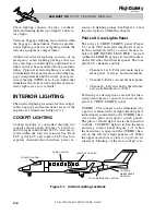
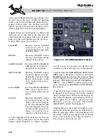
Map Lights
Two multi-directional, goose-neck map lights
are located in the cockpit, one on each side
(Figure 3-5). Power is provided to each light by
the left essential bus and is protected by a cir-
cuit breaker labeled “MAP” which is located
on the pilot circuit breaker panel in the LIGHTS
group. Dimming is controlled by a rheostat lo-
cated at the base of each light assembly.
CABIN LIGHTING
General
Passenger compartment lighting consists of
entry/exit, overhead, passenger read/table, re-
freshment cabinet, NO SMOKING/FASTEN
SEAT BELT and lavatory (read/vanity) lights.
Primary cabin lighting control is through the
main entryway control panel (Figure 3-7) which
L E A R J E T 4 5
P I L O T T R A I N I N G M A N U A L
3-5
FOR TRAINING PURPOSES ONLY
FlightSafety
international
Figure 3-5. Map Light