


DISTRIBUTION SYSTEM
COMPONENTS
FUSES
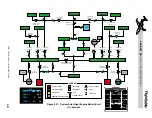
Various-sized fuses are installed throughout the
electrical system to provide circuit protection.
Each fuse will carry more than its rated capacity
for a short period of time. Extreme or pro-
longed overloading will cause a fuse to blow,
isolating a particular circuit and precluding
progressive failure of other electrical compo-
nents. Fuses can not be reset. When a fuse has
blown, it must be replaced. Fuses are located
within the aft and forward L and R Power
Distribution Panels (PDPs)(Figure 2-14).
CONTACTORS
Contactors which are particularly suited for
circuits with heavy electrical loads are used
throughout the electrical system. Contactors
are located within the aft and forward L and R
Power Distribution Panels (PDPs) (Figure 2-
14). Contactors function as remote switches to
make or break power circuits (Table 2-3). Most
of the contactors in the electrical system auto-
matically close and open for given conditions.
Some, such as the Battery, GPU and APU, are
manually selected open and closed with the re-
spective switches on the electrical control panel,
but can also open automatically if monitored
faults are detected. See Table 2-3 for conditions
under which the contactors will automatically
close/open. The table also shows which con-
tactors are normally operated manually.
CIRCUIT BREAKERS
A circuit breaker is designed to open, and in-
terrupt current flow in the event of a mal-
function. Once opened, it may be reset as
directed by the checklist or at the crew’s dis-
cretion by pushing it back in, but if it opens
again, do not reset. An open circuit breaker
may be identified by it’s white base which
can only be seen when it is open.
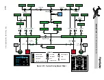
Most of the airplane's circuit breakers are lo-
cated on two circuit-breaker panels in the
cockpit, one on the pilot’s left side panel and
one on the copilot’s right side panel.
The circuit breakers are thermal type mecha-
nisms and the amperage ratings are stamped
on the top of each circuit breaker.
CIRCUIT BREAKER PANELS
On the Learjet 45 airplanes, the circuit break-
ers are grouped by systems rather than by
busses (see Figures 2-15 and 2-16).
Emergency bus circuit breakers have red rings
around them to easily distinguish them.
The individual circuit breaker labels, group-
ing labels and dividing lines are illuminated
with electro-luminescent lighting. There are
no bulbs in the panels, but the panels glow
when current is flowing through wires imbed-
ded in them. The silk-screened panels allow
light to shine through the lettering on the pan-
els. The intensity of the lighting is controlled
with the CB PANEL rheostat located on the
pilot’s and copilot’s CREW LIGHTS panels.
L E A R J E T 4 5
P I L O T T R A I N I N G M A N U A L
2-18
FOR TRAINING PURPOSES ONLY
FlightSafety
international
Figure 2-14. Aft Power Distribution Panel