


perature sensor, stall warning vanes, total tem-
perature (TAT) probe, and the windshield.
Engine bleed air is used to heat leading edge
surfaces of the wings, horizontal stabilizer, and
the engine nacelle inlets. The engine fan spin-
ner is unheated.
NOTE
All anti-ice systems require electri-
cal power to operate except the en-
gine nacelle inlet heating systems
which fail ON when electrical power
is not available to their respective
anti-icing valves.
The WING/STAB switch should be turned on
2 minutes prior to setting takeoff power.
Appropriate takeoff power and performance
charts must be used.
If any anti-ice system fails, its circuit breaker
should be checked and reset as necessary.
The anti-ice systems must be turned on before
icing conditions are encountered.
ENGINE ANTI-ICE SYSTEM
The engine nacelle anti-ice system provides
protection for the engine nacelle inlet lips and
the engine inlet pressure/temperature sensors
(Pt
2
Tt
2
) located in the engine intakes. The en-
gine nacelles are heated with engine bleed-air.
The engine inlet pressure/temperature sensors
are electrically heated whenever the corre-
sponding nacelle anti-icing system is turned on.
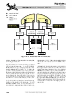
Each engine nacelle anti-ice system consists
of a bleed air duct, a nacelle anti-ice pressure
switch, a nacelle anti-ice shutoff valve, a na-
celle anti-ice switch, a caution annunciation
on the EICAS and a circuit breaker. As illus-
trated in Figure 10-3, the shutoff valve and the
pressure switches are located within each en-
gine pylon. The bleed-air duct is located within
each engine nacelle inlet lip, and distributes
bleed-air throughout the inlet lip. The dif-
fuser is connected to the engine bleed air reg-
ulated pressure duct by the nacelle anti-ice
duct. After circulating around the inlet lip,
excess bleed-air is vented overboard through
a hole at the bottom of the nacelle lip.
Nacelle Heat Switches
The two lower switches on the ANTI-ICE con-
trol panel are labeled L NAC and R NAC.
When selected, these pushbutton switch/in-
dicators provide engine bleed-air to the nacelle
inlet lip areas of each engine through the na-
celle anti-ice shutoff valves (Figure 10-3) and
energize the heat elements in the Pt
2
Tt
2
probes.
Once the shutoff valves have been opened,
bleed-air then passes through the pressure
switch, which is activated open at 6.5 psi.
Each engine anti-ice system is independently
controlled.
Each switch/indicator annunciates ON when
the S/I is depressed indicating the engine anti-
icing systems are selected. When the systems
are OFF the switches are blank.
Electrical power to operate the engine anti-ice
systems is 28 VDC power, provided by re-
spective left and right main busses. Each side
is protected by circuit breakers labeled L or
R HEAT NAC, located within the ANTI-ICE
group on the pilot and copilot circuit breaker
panels.
The nacelle anti-ice shutoff valve is pressure
actuated and solenoid controlled. Electrical
power is applied to the solenoid to close the
nacelle anti-ice shutoff valve and when the
NAC heat switches are turned on, the valves
are depowered open. Loss of electrical power
will cause the valves to open when the corre-
sponding engine is running.
10-4
FOR TRAINING PURPOSES ONLY
L E A R J E T 4 5
P I L O T T R A I N I N G M A N U A L
FlightSafety
international