bleed-air is routed directly into the cabin area,
by-passing the ECU and temperature control
valves. If the loss was due to an obstruction or
leak in the tailcone bleed-air ducting this would
restore cabin pressurization. Since the ECU is
by-passed, the LP bleed-air will be very hot.
NOTE
Crew and cabin temperature controls
are inoperative in the emergency
pressurization mode and the cabin
and cockpit will become hot.
Depressing the EMER PRESS switch will ex-
tinguish the “ON” legend in the S/I, extin-
guish the amber “LR EMER PRESS ON” CAS
message and restore normal pressurization.
If the malfunction has not been cleared and the
airplane is still at a high altitude, the cabin may
start to climb again. Emergency pressurization
can be re-activated by depressing the EMER
PRESS switch or the CPC will re-activate it
automatically at 9,500'/14,500'.
In the event it is not possible to restore nor-
mal pressurization and the situation makes it
necessary to stay in the emergency pressur-
ization mode for an extended period, it will be-
come very hot in the cabin, especially at higher
power settings. Temperature control will only
be possible by reducing engine power or by
turning one BLEED switch to OFF. At a safe
altitude, not requiring pressurization, both
BLEED switches can be selected OFF.
NOTE
When emergency pressurization is
activated, HP bleed-air will still be
available for wing and stabilizer anti-
ice as long as at least one BLEED S/I
is on. Nacelle anti-ice operation is
not affected by use of emergency
pressurization.
SERVO AIR SYSTEM
The servo air system receives HP bleed-air
from ducting located between the engine and
the HP SOV. The bleed-air is regulated to 15
+ 1 psi by the servo air pressure regulating
valve and then distributed via tubing to the sys-
tems that use it.
Servo air is used to supply actuation power for
the cockpit and cabin temperature control
valves, the low-limit temperature control valve
on the ECU, and to pressurize the hydraulic
reservoir. It is also used in the pressurization
jet pump to generate a vacuum source for out-
flow valve control.
PNEUMATIC SYSTEM
INDICATIONS AND DISPLAYS
Pneumatic system indications and displays
are limited to alerting the crew to conditions
through CAS messages and CWP annuncia-
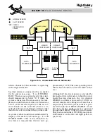
tors which are illustrated in Table 9-2 and in
Figure 9-6.
PACK CONTROL VALVE
The PACK Bi-Level Pressure Regulating and
Shut-Off Valve (PRSOV)(Figure 9-2) is con-
trolled through the PACK switch located on
the Pressurization control panel (Figure 9-
1). When the PACK switch/indicator is se-
lected On, this valve regulates the engine or
APU (if installed) bleed-air supply pressure
to the ECU for cabin pressurization and tem-
perature control. If the PACK switch indi-
cates “OFF,” engine bleed-air is prevented
from entering the ECU; although, pressur-
ization of the cabin through the emergency
pressurization system is still possible with
the PACK switch OFF. When the PACK switch
is selected ON, the PACK Bi-Level PRSOV
is de-energized open. It takes 28 VDC power
from the Left Essential bus, through the PACK
circuit breaker to close the valve when the
PACK switch is selected to OFF. The PACK
circuit breaker is located in the ENVIRON-
MENTAL group on the pilot’s circuit breaker
panel.
9-12
FOR TRAINING PURPOSES ONLY
L E A R J E T 4 5
P I L O T T R A I N I N G M A N U A L
FlightSafety
international


