


head light control from the main entryway
control panel is disabled. Both overhead lights
are powered by the right main bus and are pro-
tected by the OVRHD circuit breaker within
the CABIN group on the copilot’s circuit
breaker panel. When the pilot’s overhead light
is controlled via the main entryway switch, it
receives power from the airplane hot bus sys-
tem.
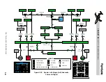
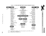
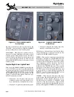
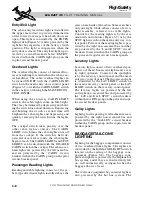
INSTR – The pilot’s instrument panel light-
ing is controlled via the INSTR rheostat and
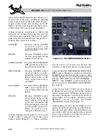
is grouped as illustrated in Figure 3-2. The dis-
play units and the radio management units
have their own brightness control, however, the
bezel control backlighting for these units is
controlled by the INSTR rheostat. The pilot in-
strument panel lights receive 28 VDC power
from the left main bus and are protected by a
circuit breaker labeled “L INSTR” located
within the LIGHTS group on the pilot circuit
breaker panel. The pilot’s INSTR rheostat also
controls the brightness of the GEN AMPS dis-
play on the APU control panel (if installed).
FLOOD – The entire instrument panel can be
illuminated by a fluorescent floodlight located
beneath the glareshield. Dimming is controlled
via this rheostat located on the L CREW
LIGHTS panel. Power to the floodlight is from
L E A R J E T 4 5
P I L O T T R A I N I N G M A N U A L
3-3
FOR TRAINING PURPOSES ONLY
FlightSafety
international
THROTTLE
QUADRANT
ENGINE/FUEL PANEL
FLIGHT
MGMT
SYSTEM
APU
TRIM
HF
SELCAL
WX RADAR
SYS TEST/CDH
PILOT'S
PRIMARY
FLIGHT
DISPLAY
EICAS
AUDIO
CWP
RMU-1
RMU-2
MULTI-
FUNCTION
DISPLAY
CO-PILOT'S
PRIMARY
FLIGHT
DISPLAY
AUDIO
DISPLAY
CONTROLLER
DISPLAY
CONTROLLER
FLIGHT GUIDANCE
CONTROLLER
1
1
2
2
3
3
4
5
6
7
7
8
8
9
9
10
11
12
13
14
15
16
17
1 - L/R DISPLAY UNIT REV PANEL
2 - L/R AOA INDICATOR (OPTIONAL)
3 - L/R DIGITAL CHRONOMETER
4 - STANDBY AIRSPEED INDICATOR
5 - STANDBY ATTITUDE INDICATOR
6 - STANDBY ALTIMETER
7 - L/R RUDDER PEDAL ADJUSTMENT
8 - L/R CREW LIGHTS PANEL
9 - L/R AHRS PANEL
10 - ELECTRICAL CONTROL PANEL
11 - REVERSION CONTROL PANEL
12 - ANTI-ICE PANEL
13 - AIRPLANE LIGHT CONTROL
14 - GEAR/HYDRAULIC PANEL
15 - CABIN PRESS/OXYGEN PANEL
16 - ENVIRONMENTAL CONTROL
17 - CVR CONTROL PANEL
DU-1
DU-2
DU-3
DU-4
L INSTR
R INSTR
PEDESTAL
Figure 3-2. Cockpit Lighting