Segment design
When designing a FISCO fieldbus segment a few requirements need to be considered.
Cabling has to comply with FISCO requirements as described in
.
You will also have to ensure that the total operating current of the connected field devices
is within the output capability of the Rosemount 2410 Tank Hub. The 2410 is able to
deliver 250
mA. Consequently, the number of field devices has to be considered so that
the total current consumption is less than 250 mA, see
Another requirement is to ensure that all field devices have at least 9 V input voltage at
their terminals. Therefore you will have to take into account the voltage drop in the
fieldbus cables.
Distances are normally quite short between the Rosemount 2410 Tank Hub and field
devices on the tank. In many cases you can use existing cables as long as the FISCO
requirements are fulfilled (see
Cable selection for the Tankbus
).
See chapter “The Tankbus” in the Rosemount 2410 Tank Hub
for more
information on segment design of a Rosemount Tank Gauging system.
3.4.8
Typical installation
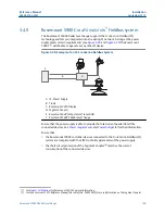
The example below (
) illustrates a system with daisy-chained field devices on a
single tank. Terminators are installed at both ends of the fieldbus segment as required in a
F
OUNDATION
Fieldbus system. In this case terminators are enabled in the Rosemount 2410
Tank Hub and a field device at the end of the network segment.
In addition to the field instruments on the Tankbus,
illustrates how an
instrument such as a pressure transmitter can be connected to the intrinsically safe 4 -20
mA analog input of the 2410 Tank Hub.
Maximum number of HART Slave Devices:
Passive current loop: 5
Active current loop: 3
(6)
In Smart Wireless Systems the 2410 can deliver 200 mA on the Tankbus
Reference Manual
Installation
00809-0100-5901
September 2019
Rosemount 5900C Radar Level Gauge
107
Summary of Contents for Rosemount 5900C
Page 1: ...Reference Manual 00809 0100 5901 Rev DA September 2019 Rosemount 5900C Radar Level Gauge ...
Page 6: ...Contents Reference Manual September 2019 00809 0100 5901 vi Reference Manual ...
Page 12: ...Introduction Reference Manual September 2019 00809 0100 5901 12 Reference Manual ...
Page 116: ...Installation Reference Manual September 2019 00809 0100 5901 116 Reference Manual ...
Page 204: ...Configuration Reference Manual September 2019 00809 0100 5901 204 Reference Manual ...
Page 208: ...Operation Reference Manual September 2019 00809 0100 5901 208 Reference Manual ...
Page 290: ...Product Certifications Reference Manual September 2019 00809 0100 5901 290 Reference Manual ...


