Note
It is important that the Inner Diameter of the still-pipe is properly configured. Open
the
Antenna
tab in case you would like to verify the Inner Diameter configuration.
See
for more information on still-pipe
requirements for the Rosemount 5900C with LPG/LNG Antenna.
F
OUNDATION
Fieldbus parameter:
TRANSDUCER 1100>CALIBRATION_DIST
14. Select the
Pin Setup
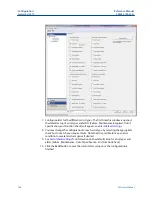
tab to configure the Verification Pin.
15. Enter nominal position. Normally, there is one verification pin placed at 2500 mm
below the flange. In case there are two or three verification pins, enter nominal
position for each one. In addition to that, a calibration ring should be installed at the
bottom end of the still-pipe. It will be used for calibrating the tank geometry
parameters. See
for more information.
The Pipe Expansion Factor lets you compensate for thermal expansion of the still-
pipe.
F
OUNDATION
Fieldbus parameters:
TRANSDUCER 1500>LPG_NUMBER_OF_PINS
TRANSDUCER 1500>LPG_PIN1_CONFIGURATION
TRANSDUCER 1500>LPG_PIN2_CONFIGURATION
TRANSDUCER 1500>LPG_PIN3_CONFIGURATION
TRANSDUCER 1500>LPG_PIN_TEMPERATURE
TRANSDUCER 1500>LPG_PIN_TEMP_EXP_PPM
Configuration
Reference Manual
September 2019
00809-0100-5901
200
Reference Manual
Summary of Contents for Rosemount 5900C
Page 1: ...Reference Manual 00809 0100 5901 Rev DA September 2019 Rosemount 5900C Radar Level Gauge ...
Page 6: ...Contents Reference Manual September 2019 00809 0100 5901 vi Reference Manual ...
Page 12: ...Introduction Reference Manual September 2019 00809 0100 5901 12 Reference Manual ...
Page 116: ...Installation Reference Manual September 2019 00809 0100 5901 116 Reference Manual ...
Page 204: ...Configuration Reference Manual September 2019 00809 0100 5901 204 Reference Manual ...
Page 208: ...Operation Reference Manual September 2019 00809 0100 5901 208 Reference Manual ...
Page 290: ...Product Certifications Reference Manual September 2019 00809 0100 5901 290 Reference Manual ...


