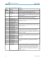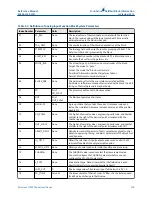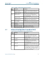
Table C-4: Analog Output Function Block System Parameters
(continued)
Parameter
Units
Description
BLOCK_ERR
None
The summary of active error conditions associated with the
block. The block errors for the AnalogOutput block are
Simulate Active, Input Failure/Process Variable has Bad
Status,Output Failure, Read back Failed, and Out of Service..
CAS_IN
EU of PV_SCALE The remote setpoint value from another function block.
IO_OPTS
None
Allows you to select how the I/O signals are processed. The
supported I/O options for the AO function block are SP_PV
Track in Man, Increase to Close, and Use PV for BKCAL_OUT.
CHANNEL
None
Defines the output that drives the field device.
See
MODE
None
Enumerated attribute used to request and show the source of
the setpoint and/or output used by the block.
OUT
EU of XD_SCALE The primary value and status calculated by the block in Auto
mode. OUT may be set manually in Man mode.
PV
EU of PV_SCALE The process variable used in block execution. This value is
converted from READBACK to show the actuator position in
the same units as the setpoint value.
PV_SCALE
None
The high and low scale values, the engineering units code, and
the number of digits to the right of the decimal point
associated with the PV.
READBACK
EU of XD_SCALE The measured or implied actuator position associated with
the OUT value.
SIMULATE
EU of XD_SCALE Enables simulation and allows you to enter an input value and
status.
SP
EU of PV_SCALE The target block output value (setpoint).
SP_HI_LIM
EU of PV_SCALE The highest setpoint value allowed.
SP_LO_LIM
EU of PV_SCALE The lowest setpoint value allowed.
SP_RATE_DN
EU of PV_SCALE
per second
Ramp rate for downward setpoint changes. When the ramp
rate is set to zero, the setpoint is used immediately.
SP_RATE_UP
EU of PV_SCALE
per second
Ramp rate for upward setpoint changes. When the ramp rate
is set to zero, the setpoint is used immediately.
SP_WRK
EU of PV_SCALE The working setpoint of the block. It is the result of setpoint
rate-of-change limiting. The value is converted to percent to
obtain the block’s OUT value.
C.3.1
Setting the output
To set the output for the AO block, you must first set the mode to define the manner in
which the block determines its setpoint. In Manual mode the value of the output attribute
(OUT) must be set manually by the user, and is independent of the setpoint. In Automatic
mode, OUT is set automatically based on the value specified by the setpoint (SP) in
F
OUNDATION
™
Fieldbus Block Information
Reference Manual
September 2019
00809-0100-5901
302
Reference Manual
Summary of Contents for Rosemount 5900C
Page 1: ...Reference Manual 00809 0100 5901 Rev DA September 2019 Rosemount 5900C Radar Level Gauge ...
Page 6: ...Contents Reference Manual September 2019 00809 0100 5901 vi Reference Manual ...
Page 12: ...Introduction Reference Manual September 2019 00809 0100 5901 12 Reference Manual ...
Page 116: ...Installation Reference Manual September 2019 00809 0100 5901 116 Reference Manual ...
Page 204: ...Configuration Reference Manual September 2019 00809 0100 5901 204 Reference Manual ...
Page 208: ...Operation Reference Manual September 2019 00809 0100 5901 208 Reference Manual ...
Page 290: ...Product Certifications Reference Manual September 2019 00809 0100 5901 290 Reference Manual ...


