
Product Description
85
Notice:
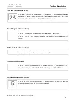
While the tractor is working, the driver should always pay attention to the various instruments and
indicator lamps, and if any abnormality occurs, stop it immediately for maintenance.
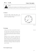
Tachometer
After startup of engine, it indicates engine speed (r / min,
representing revolutions per minute). The value on the LCD
represents the operating hours of engine.
Fig. 3-13
Fuel gauge
Fuel gauge is used to indicate remaining fuel in the fuel tank.
The pointer moving to the right indicates that the tank is full
of fuel. The pointer moving to the left (red zone) indicates that
the remaining fuel in the fuel tank is less than 1/8 the fuel tank
capacity.
During use of the tractor, there being no or little fuel in fuel
tank with the pointer being still in the right green zone
indicates occurrence of short circuit of the fuel level sensor or
fuel gauge; the fuel tank being full with the pointer being still
in the left red zone indicates occurrence of open circuit of the
fuel level sensor or fuel gauge. In both cases, inspection and
repair are required.
Fig. 3-14
Water temperature gauge
Summary of Contents for FL35-70HP Series
Page 21: ...Product Mark 20 1 Security Considerations ...
Page 57: ...Product Mark 56 Fig 1 35 Fig 1 36 ...
Page 58: ...Product Mark 57 Fig 1 37 Fig 1 38 ...
Page 70: ...69 2 Product Mark ...
Page 74: ...73 Page Left Intentionally Blank ...
Page 75: ...Product Description 74 3 Product Description ...
Page 77: ...Product Description 76 Fig 3 2 3 1 2 Appearance of tractor equipped with cab ...
Page 81: ...Product Description 80 ...
Page 113: ...Product Description 112 ...
Page 124: ...Electrical system 123 4 Operation Instructions ...
Page 157: ...Electrical system 156 ...
Page 162: ...Electrical system 161 Fig 4 32 Three point linkage Model 2 ...
Page 189: ...Electrical system 188 5 Wheels ...
Page 208: ...Electrical system 207 6 Electrical System ...
Page 230: ...Electrical system 229 requirements 6 6 Electrical Schematic Diagram ...
Page 235: ...234 7 On board Spare Parts Tools and Quick wear Parts ...
Page 241: ...240 ...
Page 242: ...241 8 Maintenance Specification ...
Page 288: ...287 Fig 8 35 ...
Page 338: ...Operation Instructions 337 9 Troubleshooting ...
Page 353: ...352 10 Tractor Storage and Unpack ...
Page 358: ...Tractor Storage and Unpack 357 11 Delivery Acceptance and Transportation ...
Page 361: ...360 ...
Page 362: ...361 12 Disassembly and Disposal ...
Page 365: ...Warranty Contents 364 13 Warranty Contents ...
Page 411: ...Appendix 410 15 Appendix ...











![Whirlpool [12:36:03] ?????????????????: GC900QPPB Use & Care Manual preview](http://thumbs.mh-extra.com/thumbs/whirlpool/12-36-03-gc900qppb/12-36-03-gc900qppb_use-and-care-manual_437149-01.webp)

