


Product Description
101
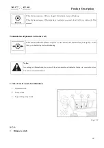
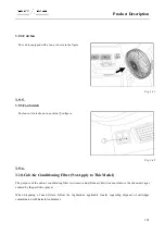
The heating system can be turned on and off using the control
switch at the cab roof.
Fig. 3-39
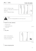
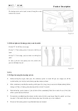
3.9.2.Description of heating system control switch
Position “0”: Cut off the power supply.
Position “1”: The heating system is turned on with low air
speed.
Position “2”: The heating system is turned on with high air
speed.
To warm up the cab more quickly, move the switch to the
position with high air speed.
Fig. 3-40
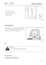
3.9.3.
3.9.3.Tips for using the heating system
●
Before starting the engine, make sure the ventilation system is turned off (you can simply turn off the
ventilation fan), to avoid the tractor battery operation under overload.
●
If the ventilation system has been running at full power for a long time, do not turn it off immediately. Before
turning it off, have it running at minimum speed for at least 20 seconds.
●
With the heating system turned on, you can feel air flow immediately from the air outlet. If no air flow, turn
off the system and locate the fault.
●
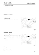
To demist the windshield quickly, simply turn the control switch to max speed. Open the outlet 3, and close
the outlet 1. This ensures that the entire stream of warm air flows directly to the windshield.
●
Do not use the heating system in a particularly dusty environment.
Summary of Contents for FL35-70HP Series
Page 21: ...Product Mark 20 1 Security Considerations ...
Page 57: ...Product Mark 56 Fig 1 35 Fig 1 36 ...
Page 58: ...Product Mark 57 Fig 1 37 Fig 1 38 ...
Page 70: ...69 2 Product Mark ...
Page 74: ...73 Page Left Intentionally Blank ...
Page 75: ...Product Description 74 3 Product Description ...
Page 77: ...Product Description 76 Fig 3 2 3 1 2 Appearance of tractor equipped with cab ...
Page 81: ...Product Description 80 ...
Page 113: ...Product Description 112 ...
Page 124: ...Electrical system 123 4 Operation Instructions ...
Page 157: ...Electrical system 156 ...
Page 162: ...Electrical system 161 Fig 4 32 Three point linkage Model 2 ...
Page 189: ...Electrical system 188 5 Wheels ...
Page 208: ...Electrical system 207 6 Electrical System ...
Page 230: ...Electrical system 229 requirements 6 6 Electrical Schematic Diagram ...
Page 235: ...234 7 On board Spare Parts Tools and Quick wear Parts ...
Page 241: ...240 ...
Page 242: ...241 8 Maintenance Specification ...
Page 288: ...287 Fig 8 35 ...
Page 338: ...Operation Instructions 337 9 Troubleshooting ...
Page 353: ...352 10 Tractor Storage and Unpack ...
Page 358: ...Tractor Storage and Unpack 357 11 Delivery Acceptance and Transportation ...
Page 361: ...360 ...
Page 362: ...361 12 Disassembly and Disposal ...
Page 365: ...Warranty Contents 364 13 Warranty Contents ...
Page 411: ...Appendix 410 15 Appendix ...