Electrical system
204
Important:
Remove the ballast need complete the above operation in an opposite manner.
●
➢
Wheel metal disc
The metal disc must be installed by at least two workers – One undertakes to lift the metal disc up in place while
the other uses bolts to fix it.
Danger:
Please make sure to check the weight of each load. If it weighs more than the bearable limit (male: 30
kg, female: 20 kg), please use appropriate mechanical lifting devices.
5.6.2.Tractor ballast
➢
Front ballast
Notice:
When a tractor has large farm implement engaged in the rear, for your safety, it must be equipped with
enough front ballast, otherwise, rollover risks may happen!
➢
In order to adjust the front and rear ballast distribution, it is necessary to install front ballast in the front of the
tractor. For heavy-load ploughing or large sowing implement, etc. engaged, front ballast must be equipped in order
to prevent the tractor head holding up and ensure the driving safety.
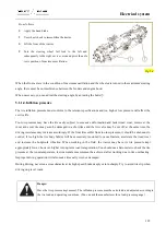
For the FL35-70HP series tractor, the ballast consists of a ballast bracket, a draw lug, and ballast blocks.
The ballast bracket must be directly fixed onto the tractor.
The bracket weight is 45kg.
1.
Ballast bracket;
2.
Mounting bracket
3.
Fixing bolt
Fig. 5-14
Summary of Contents for FL35-70HP Series
Page 21: ...Product Mark 20 1 Security Considerations ...
Page 57: ...Product Mark 56 Fig 1 35 Fig 1 36 ...
Page 58: ...Product Mark 57 Fig 1 37 Fig 1 38 ...
Page 70: ...69 2 Product Mark ...
Page 74: ...73 Page Left Intentionally Blank ...
Page 75: ...Product Description 74 3 Product Description ...
Page 77: ...Product Description 76 Fig 3 2 3 1 2 Appearance of tractor equipped with cab ...
Page 81: ...Product Description 80 ...
Page 113: ...Product Description 112 ...
Page 124: ...Electrical system 123 4 Operation Instructions ...
Page 157: ...Electrical system 156 ...
Page 162: ...Electrical system 161 Fig 4 32 Three point linkage Model 2 ...
Page 189: ...Electrical system 188 5 Wheels ...
Page 208: ...Electrical system 207 6 Electrical System ...
Page 230: ...Electrical system 229 requirements 6 6 Electrical Schematic Diagram ...
Page 235: ...234 7 On board Spare Parts Tools and Quick wear Parts ...
Page 241: ...240 ...
Page 242: ...241 8 Maintenance Specification ...
Page 288: ...287 Fig 8 35 ...
Page 338: ...Operation Instructions 337 9 Troubleshooting ...
Page 353: ...352 10 Tractor Storage and Unpack ...
Page 358: ...Tractor Storage and Unpack 357 11 Delivery Acceptance and Transportation ...
Page 361: ...360 ...
Page 362: ...361 12 Disassembly and Disposal ...
Page 365: ...Warranty Contents 364 13 Warranty Contents ...
Page 411: ...Appendix 410 15 Appendix ...


