


Electrical system
125
firmly and reliably, individual control mechanisms work normally, individual pipe connections are tightened
firmly, or oil leakage, water leakage or air leakage takes place.
●
Inspect lubricating oil level of engine oil pan, tractor transmission, rear axle and hydraulic system. Replenish
sufficient cooling water in the water tank radiator. Enough fuel should be filled in the fuel tank.
●
Pull the fuel circuit switch handle of the fuel tank to flow direction of the fuel pipe, so that the fuel circuit is
connected.
●
Inspect the transmission control lever and PTO shaft control handle, and set the main shift lever, PTO control
handle, front drive axle control handle to neutral position, and the distributor control handle to neutral position.
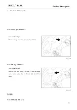
●
Pull up the shutdown cable locking device so that the shutdown cable withdraws and the fuel pump can supply
fuel.
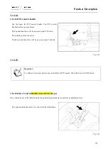
●
Set the hand throttle to semi-opening state.
●
For the tractor that is new, overhauled or is not used for a long time, remove air trapped in oil circuit prior to
startup, so as to ensure smooth startup of the diesel engine. The method is as follows: First loosen the vent
screw of the diesel filter, and use a hand pump to pump fuel to remove the air trapped in the pipe section from
the fuel tank to the diesel filter, until no air bubbles exist in the drained fuel. Then, tighten the vent screw of
the diesel filter, loosen the vent screw on the fuel injection pump, and remove the air by the same method until
no bubbles exist in the drained fuel.
Important:
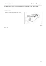
Foreign bodies should be removed regularly from the water tank screen, so as to avoid fault due to
improper heat radiation of the engine.
●
Important:
After the tractor is installed with a backsack harvester, due to bad radiation conditions during the field
working, it is recommended that an auxiliary radiation device is installed at appropriate position on the
tractor to ensure long-time continuous working of the engine.
4.3.2.Start the engine
Summary of Contents for FL35-70HP Series
Page 21: ...Product Mark 20 1 Security Considerations ...
Page 57: ...Product Mark 56 Fig 1 35 Fig 1 36 ...
Page 58: ...Product Mark 57 Fig 1 37 Fig 1 38 ...
Page 70: ...69 2 Product Mark ...
Page 74: ...73 Page Left Intentionally Blank ...
Page 75: ...Product Description 74 3 Product Description ...
Page 77: ...Product Description 76 Fig 3 2 3 1 2 Appearance of tractor equipped with cab ...
Page 81: ...Product Description 80 ...
Page 113: ...Product Description 112 ...
Page 124: ...Electrical system 123 4 Operation Instructions ...
Page 157: ...Electrical system 156 ...
Page 162: ...Electrical system 161 Fig 4 32 Three point linkage Model 2 ...
Page 189: ...Electrical system 188 5 Wheels ...
Page 208: ...Electrical system 207 6 Electrical System ...
Page 230: ...Electrical system 229 requirements 6 6 Electrical Schematic Diagram ...
Page 235: ...234 7 On board Spare Parts Tools and Quick wear Parts ...
Page 241: ...240 ...
Page 242: ...241 8 Maintenance Specification ...
Page 288: ...287 Fig 8 35 ...
Page 338: ...Operation Instructions 337 9 Troubleshooting ...
Page 353: ...352 10 Tractor Storage and Unpack ...
Page 358: ...Tractor Storage and Unpack 357 11 Delivery Acceptance and Transportation ...
Page 361: ...360 ...
Page 362: ...361 12 Disassembly and Disposal ...
Page 365: ...Warranty Contents 364 13 Warranty Contents ...
Page 411: ...Appendix 410 15 Appendix ...