Electrical system
190
Tire installation
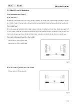
When installing a tire, first check whether the rim and tire are
matched, make sure that there is no burr or serious deformation
at the rim edge, clear the rust on the rim and then check whether
there is any damage on the tire. Before installation, rub up all
parts and apply a thin layer of talcum powder between the inner
tube and the cover tire. Put the rim flat, mount the cover tire and
step or use a crowbar to pry it into the rim. Put the inner tube in
(the cover tire can be slightly padded up) and use a lead wire to
fix the tire valve in the valve hole on the rim to prevent it
slipping off. Use a crowbar to pry the other side of the cover tire
into the wheel rim (it is most difficult at last, but you can use a
hammer to tap the crowbar as shown in the figure). Finally
check whether the valve position is skewed and whether the tire
edge and rim fit tightly. During inflating, check whether the
inner tube is broken, inflate it and use a hammer to knock at the
cover tire until the regulated pressure has been achieved, and
then half discharge and inflate it again, so that the inner tube
could expand normally and eliminate cockles. While installing
a tire onto the tractor, attention also must be paid to the direction
of the tire pattern; otherwise it will affect the adhesion
performance and wear resistance, and have mud easily
gathering.
Fig. 5-2
Danger:
Never dismantle any tire, wheel hub or spokes, as well as the connecting bolts between spokes and wheel
rims; otherwise, the tire may fly out to cause injuries!
Summary of Contents for FL35-70HP Series
Page 21: ...Product Mark 20 1 Security Considerations ...
Page 57: ...Product Mark 56 Fig 1 35 Fig 1 36 ...
Page 58: ...Product Mark 57 Fig 1 37 Fig 1 38 ...
Page 70: ...69 2 Product Mark ...
Page 74: ...73 Page Left Intentionally Blank ...
Page 75: ...Product Description 74 3 Product Description ...
Page 77: ...Product Description 76 Fig 3 2 3 1 2 Appearance of tractor equipped with cab ...
Page 81: ...Product Description 80 ...
Page 113: ...Product Description 112 ...
Page 124: ...Electrical system 123 4 Operation Instructions ...
Page 157: ...Electrical system 156 ...
Page 162: ...Electrical system 161 Fig 4 32 Three point linkage Model 2 ...
Page 189: ...Electrical system 188 5 Wheels ...
Page 208: ...Electrical system 207 6 Electrical System ...
Page 230: ...Electrical system 229 requirements 6 6 Electrical Schematic Diagram ...
Page 235: ...234 7 On board Spare Parts Tools and Quick wear Parts ...
Page 241: ...240 ...
Page 242: ...241 8 Maintenance Specification ...
Page 288: ...287 Fig 8 35 ...
Page 338: ...Operation Instructions 337 9 Troubleshooting ...
Page 353: ...352 10 Tractor Storage and Unpack ...
Page 358: ...Tractor Storage and Unpack 357 11 Delivery Acceptance and Transportation ...
Page 361: ...360 ...
Page 362: ...361 12 Disassembly and Disposal ...
Page 365: ...Warranty Contents 364 13 Warranty Contents ...
Page 411: ...Appendix 410 15 Appendix ...


