


Electrical system
189
5.1.Introduction
5.1.1.Basic introduction of tires
5.1.1.1.Optional tires
Tires are the main quick-wear parts of tractors, so we must pay attention to the use and maintenance of tires, so that
the service life could be prolonged as much as possible.
Each tire should have a specified load value, overload can make tires excessively deformed or broken easily due to
lateral overbending; moreover, the tire body fabrics and buffer layers are apt to degumming, which will thus result
in fabric layer looseness and even tire burst especially on rough roads or at the impact of obstacles.
During service, have tires not stained with oil, acid or alkali and other chemical corrosives and avoid exposure in
the scorching sun, lest the rubber go bad due to aging. Often check whether the wheel alignment and toe-in is right,
so as to prevent tire eccentric wear. When the wheel tread is unevenly worn, transpose the left and right tires before
continuous use.
Notice:
The tire replacement is of risks, so such operation must be completed by professionals with professional
equipment in accordance with the operating manual provided by the tire and wheel manufacturers.
Mismatched tires and wheels may cause damages, tire explosion and even injuries or death. Never install
or use any damaged tire or wheel.
5.1.1.2.Steps for correct installation of tires
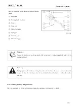
Tire disassembly
Use special tools during tire disassembly but never use sharp or
tough tools (such as screwdrivers) or hammers to knock at will,
so as not to puncture the tires or damage the tire edges or wheel
rims.
Before removing a tire, first deflate it, press the cover tire edges
on both sides into the groove of the wheel rim, use a crowbar to
force the tire edge on one side near the tire valve out from the
wheel rim, and then use two crowbars to pry out the whole tire
edge in an alternative manner. Remove the inner tube, then pry
out the tire edge on the other side in the same way and finally
remove the cover tire.
Fig. 5-1
Summary of Contents for FL35-70HP Series
Page 21: ...Product Mark 20 1 Security Considerations ...
Page 57: ...Product Mark 56 Fig 1 35 Fig 1 36 ...
Page 58: ...Product Mark 57 Fig 1 37 Fig 1 38 ...
Page 70: ...69 2 Product Mark ...
Page 74: ...73 Page Left Intentionally Blank ...
Page 75: ...Product Description 74 3 Product Description ...
Page 77: ...Product Description 76 Fig 3 2 3 1 2 Appearance of tractor equipped with cab ...
Page 81: ...Product Description 80 ...
Page 113: ...Product Description 112 ...
Page 124: ...Electrical system 123 4 Operation Instructions ...
Page 157: ...Electrical system 156 ...
Page 162: ...Electrical system 161 Fig 4 32 Three point linkage Model 2 ...
Page 189: ...Electrical system 188 5 Wheels ...
Page 208: ...Electrical system 207 6 Electrical System ...
Page 230: ...Electrical system 229 requirements 6 6 Electrical Schematic Diagram ...
Page 235: ...234 7 On board Spare Parts Tools and Quick wear Parts ...
Page 241: ...240 ...
Page 242: ...241 8 Maintenance Specification ...
Page 288: ...287 Fig 8 35 ...
Page 338: ...Operation Instructions 337 9 Troubleshooting ...
Page 353: ...352 10 Tractor Storage and Unpack ...
Page 358: ...Tractor Storage and Unpack 357 11 Delivery Acceptance and Transportation ...
Page 361: ...360 ...
Page 362: ...361 12 Disassembly and Disposal ...
Page 365: ...Warranty Contents 364 13 Warranty Contents ...
Page 411: ...Appendix 410 15 Appendix ...