305
①
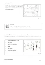
Cover of radiator
②
Water tank of radiator
③
Water drain valve
Cleaning of incrustation of cooling system
Before maintenance, solution containing 750g caustic soda
and 150g kerosene in every 10L water will be filled in the
cooling system. The engine will be operated at
intermediate speed for 5 min to 10min, solution will be
stayed for 10h to 12h (attention: thermal insulation
measures must be adopted in the winter to prevent
freezing), then, the engine will be re-started for operating
at intermediate speed for 20 min, and stopped for
discharging cleanout fluid.
After the engine has been cooled, water pipe will be
inserted into water tank
②
for flushing and water drain
valve
③
in the bottom of the water tank shall be opened.
The water drain valve will be closed after cleaning. In
addition, water will be added to make engine operate for
several minutes, and then water will be discharged. After
the engine has been cooled, new anti-freezing solution or
cooling water will be added in accordance with provisions.
Fig. 8-54
8.10.2.Cooling system of the engine that has used anti-freezing solution
Effective period of anti-freezing solution is 2 years or 1600 h. if it exceeds this period, it shall be replaced and
cooling system shall be flushed. Then, new anti-freezing solution will be added.
Warning:
Please abide by rules for environmental protection. Any fluid (petroleum, diesel and cooling liquid)
or filter and battery must be discarded in accordance with applicable laws and regulations.
Steps for replacing cooling liquid and cleaning circuit
Summary of Contents for FL35-70HP Series
Page 21: ...Product Mark 20 1 Security Considerations ...
Page 57: ...Product Mark 56 Fig 1 35 Fig 1 36 ...
Page 58: ...Product Mark 57 Fig 1 37 Fig 1 38 ...
Page 70: ...69 2 Product Mark ...
Page 74: ...73 Page Left Intentionally Blank ...
Page 75: ...Product Description 74 3 Product Description ...
Page 77: ...Product Description 76 Fig 3 2 3 1 2 Appearance of tractor equipped with cab ...
Page 81: ...Product Description 80 ...
Page 113: ...Product Description 112 ...
Page 124: ...Electrical system 123 4 Operation Instructions ...
Page 157: ...Electrical system 156 ...
Page 162: ...Electrical system 161 Fig 4 32 Three point linkage Model 2 ...
Page 189: ...Electrical system 188 5 Wheels ...
Page 208: ...Electrical system 207 6 Electrical System ...
Page 230: ...Electrical system 229 requirements 6 6 Electrical Schematic Diagram ...
Page 235: ...234 7 On board Spare Parts Tools and Quick wear Parts ...
Page 241: ...240 ...
Page 242: ...241 8 Maintenance Specification ...
Page 288: ...287 Fig 8 35 ...
Page 338: ...Operation Instructions 337 9 Troubleshooting ...
Page 353: ...352 10 Tractor Storage and Unpack ...
Page 358: ...Tractor Storage and Unpack 357 11 Delivery Acceptance and Transportation ...
Page 361: ...360 ...
Page 362: ...361 12 Disassembly and Disposal ...
Page 365: ...Warranty Contents 364 13 Warranty Contents ...
Page 411: ...Appendix 410 15 Appendix ...


