


Product Description
117
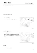
See the figure for the shuttle shift lever.
The shuttle shift lever is configured only in some models.
See
the " Power train device " for details.
Fig. 3-58
3.14.12.
3.14.12.Differential lock control pedal
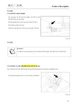
See the figure for the differential lock control pedal.
When the differential lock control pedal is stepped down, then
the differential lock will be engaged and the left and right
drive shafts are connected in a rigid manner.
Release the differential lock control pedal and then the
differential lock will disengage automatically.
Fig. 3-59
3.14.13.
3.14.13.Four-wheel drive control handle
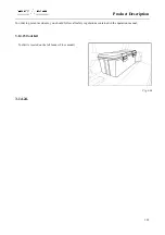
See the figure for the four-wheel drive control handle.
Pull up and the tractor 2WD mode will be changed into its
4WD mode.
Fig. 3-60
Summary of Contents for FL35-70HP Series
Page 21: ...Product Mark 20 1 Security Considerations ...
Page 57: ...Product Mark 56 Fig 1 35 Fig 1 36 ...
Page 58: ...Product Mark 57 Fig 1 37 Fig 1 38 ...
Page 70: ...69 2 Product Mark ...
Page 74: ...73 Page Left Intentionally Blank ...
Page 75: ...Product Description 74 3 Product Description ...
Page 77: ...Product Description 76 Fig 3 2 3 1 2 Appearance of tractor equipped with cab ...
Page 81: ...Product Description 80 ...
Page 113: ...Product Description 112 ...
Page 124: ...Electrical system 123 4 Operation Instructions ...
Page 157: ...Electrical system 156 ...
Page 162: ...Electrical system 161 Fig 4 32 Three point linkage Model 2 ...
Page 189: ...Electrical system 188 5 Wheels ...
Page 208: ...Electrical system 207 6 Electrical System ...
Page 230: ...Electrical system 229 requirements 6 6 Electrical Schematic Diagram ...
Page 235: ...234 7 On board Spare Parts Tools and Quick wear Parts ...
Page 241: ...240 ...
Page 242: ...241 8 Maintenance Specification ...
Page 288: ...287 Fig 8 35 ...
Page 338: ...Operation Instructions 337 9 Troubleshooting ...
Page 353: ...352 10 Tractor Storage and Unpack ...
Page 358: ...Tractor Storage and Unpack 357 11 Delivery Acceptance and Transportation ...
Page 361: ...360 ...
Page 362: ...361 12 Disassembly and Disposal ...
Page 365: ...Warranty Contents 364 13 Warranty Contents ...
Page 411: ...Appendix 410 15 Appendix ...