Electrical system
184
Important:
When the external cylinder reaches its limit travel, immediately open the control switch to relieve the
pressure, so as to protect the maximum pressure of the hydraulic circuit from being maintained for a long
time, resulting in overloading of the system.
Operation of hydraulic device requiring continuous oil
flow.
●
For example: Hydraulic motor
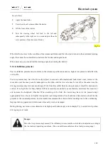
When connecting the hydraulic motor, always follow the
manufacturer's instructions. For a hydraulic motor that rotates
only in one direction, the oil return port must be connected
with the no-load discharge pipe. Connect the pressure pipeline
with the control valve. For a hydraulic motor that may rotate
in two directions, connectors required for the 2 control valve
is usually used.
Install an oil temperature sensor, and if necessary, install an
oil cooler. The allowable maximum temperature is 110°C
(230°F).
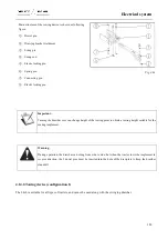
Fig. 4-63
Warning:
Do not move the control valve to neutral position immediately, because the back pressure produced may
damage the hose if the hydraulic motor is not equipped with a safety valve.
4.13.Towing Devices
Warning:
All the implements mounted on the tractor must be secured firmly and in accordance with the
manufacturer’s instructions. Use permitted devices only.
Summary of Contents for FL35-70HP Series
Page 21: ...Product Mark 20 1 Security Considerations ...
Page 57: ...Product Mark 56 Fig 1 35 Fig 1 36 ...
Page 58: ...Product Mark 57 Fig 1 37 Fig 1 38 ...
Page 70: ...69 2 Product Mark ...
Page 74: ...73 Page Left Intentionally Blank ...
Page 75: ...Product Description 74 3 Product Description ...
Page 77: ...Product Description 76 Fig 3 2 3 1 2 Appearance of tractor equipped with cab ...
Page 81: ...Product Description 80 ...
Page 113: ...Product Description 112 ...
Page 124: ...Electrical system 123 4 Operation Instructions ...
Page 157: ...Electrical system 156 ...
Page 162: ...Electrical system 161 Fig 4 32 Three point linkage Model 2 ...
Page 189: ...Electrical system 188 5 Wheels ...
Page 208: ...Electrical system 207 6 Electrical System ...
Page 230: ...Electrical system 229 requirements 6 6 Electrical Schematic Diagram ...
Page 235: ...234 7 On board Spare Parts Tools and Quick wear Parts ...
Page 241: ...240 ...
Page 242: ...241 8 Maintenance Specification ...
Page 288: ...287 Fig 8 35 ...
Page 338: ...Operation Instructions 337 9 Troubleshooting ...
Page 353: ...352 10 Tractor Storage and Unpack ...
Page 358: ...Tractor Storage and Unpack 357 11 Delivery Acceptance and Transportation ...
Page 361: ...360 ...
Page 362: ...361 12 Disassembly and Disposal ...
Page 365: ...Warranty Contents 364 13 Warranty Contents ...
Page 411: ...Appendix 410 15 Appendix ...


