306
1
Park the tractor on flat ground
The engine must be closed and cooling liquid must be
adequately cooled.
2.
Suitable vessel will be placed under the plug
screw.
3.
Open the water drain valve
③
to discharge cooling
liquid
4.
Re-close the water drain valve
③
, fill the circuit
with mixture of cleanser via the injection port on liquid
storage tank.
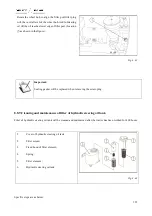
Fig. 8-55
5.
Start the engine to make it under idle running for about half an hour.
Important:
When the engine is under operation, mixture of cooling liquid in the liquid storage tank has not been
reduced to the minimum limit.
6.
Shut off the engine, exhaust the system and fill it with water; and then re-start the engine to reach about
1000rpm and operate for 5 minutes.
7.
Re-exhaust the system
8.
Cooling liquid will be used to fill the circuit so that the engine will be operated for several minutes. If
necessary, cooling liquid will be supplemented to the system.
Important:
1.
In winter, frequently check the antifreeze concentration according to ambient temperature. If
necessary, timely recover to normal concentration.
2.
As for the tractor that has not used anti-freezing solution, when water temperature is reduced
to below 70
℃
, water shall be discharged completely under the situation that the engine is under
idle running to prevent cooling water from freezing and damaging the engine.
Summary of Contents for FL35-70HP Series
Page 21: ...Product Mark 20 1 Security Considerations ...
Page 57: ...Product Mark 56 Fig 1 35 Fig 1 36 ...
Page 58: ...Product Mark 57 Fig 1 37 Fig 1 38 ...
Page 70: ...69 2 Product Mark ...
Page 74: ...73 Page Left Intentionally Blank ...
Page 75: ...Product Description 74 3 Product Description ...
Page 77: ...Product Description 76 Fig 3 2 3 1 2 Appearance of tractor equipped with cab ...
Page 81: ...Product Description 80 ...
Page 113: ...Product Description 112 ...
Page 124: ...Electrical system 123 4 Operation Instructions ...
Page 157: ...Electrical system 156 ...
Page 162: ...Electrical system 161 Fig 4 32 Three point linkage Model 2 ...
Page 189: ...Electrical system 188 5 Wheels ...
Page 208: ...Electrical system 207 6 Electrical System ...
Page 230: ...Electrical system 229 requirements 6 6 Electrical Schematic Diagram ...
Page 235: ...234 7 On board Spare Parts Tools and Quick wear Parts ...
Page 241: ...240 ...
Page 242: ...241 8 Maintenance Specification ...
Page 288: ...287 Fig 8 35 ...
Page 338: ...Operation Instructions 337 9 Troubleshooting ...
Page 353: ...352 10 Tractor Storage and Unpack ...
Page 358: ...Tractor Storage and Unpack 357 11 Delivery Acceptance and Transportation ...
Page 361: ...360 ...
Page 362: ...361 12 Disassembly and Disposal ...
Page 365: ...Warranty Contents 364 13 Warranty Contents ...
Page 411: ...Appendix 410 15 Appendix ...


