Electrical system
197
5.3.Adjustment of Wheel Tread
5.3.1.Change the wheel tread
The wheel tread can be adjusted according to different crops spacing or with different implements.
Never use a tractor before its wheel rims have been completely fixed.
The distance from the outer edge of the area illuminated by the direction indicators, the side lights, the rear sidelights
and upper reflectors, to the outer edge of the tires must not be greater than 400 mm; this rule is internationally
universal.
The data contained in the vehicle registration document regarding the maximum track widths for use on both urban
and rural public roads must be respected.
After any adjustment to the track width and whenever changing the wheels, tighten the nuts and bolts to the
following required tightening torques:
●
Front wheel
◇
Bolt M16x1.5= 271 Nm (27.6 kgm),
●
Rear wheel
◇
Nut M20x1.5= 550 Nm (56 kgm);
Before replacing any wheel, please make sure that the tractor can't move and is appropriately supported.
When working with compressed air to bed in the tire on the rim always use an extension line of sufficient length to
allow you to remain at the side of the tire. These operations must be carried out only by qualified personnel.
Notice:
When changing wheels or carrying out maintenance and repair operations, raise and support the tractor
using specific equipment only.
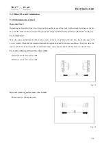
Fixed wheels
When the wheel rims are fixed, you can apply two configurations to the wheels, so that two optional front and rear
wheel treads can be available.
Important:
To change the wheel tread, please transpose the left and right wheels. In this way, the tires will not have
the driving direction changed.
Assembly drawing of front wheels
Summary of Contents for FL35-70HP Series
Page 21: ...Product Mark 20 1 Security Considerations ...
Page 57: ...Product Mark 56 Fig 1 35 Fig 1 36 ...
Page 58: ...Product Mark 57 Fig 1 37 Fig 1 38 ...
Page 70: ...69 2 Product Mark ...
Page 74: ...73 Page Left Intentionally Blank ...
Page 75: ...Product Description 74 3 Product Description ...
Page 77: ...Product Description 76 Fig 3 2 3 1 2 Appearance of tractor equipped with cab ...
Page 81: ...Product Description 80 ...
Page 113: ...Product Description 112 ...
Page 124: ...Electrical system 123 4 Operation Instructions ...
Page 157: ...Electrical system 156 ...
Page 162: ...Electrical system 161 Fig 4 32 Three point linkage Model 2 ...
Page 189: ...Electrical system 188 5 Wheels ...
Page 208: ...Electrical system 207 6 Electrical System ...
Page 230: ...Electrical system 229 requirements 6 6 Electrical Schematic Diagram ...
Page 235: ...234 7 On board Spare Parts Tools and Quick wear Parts ...
Page 241: ...240 ...
Page 242: ...241 8 Maintenance Specification ...
Page 288: ...287 Fig 8 35 ...
Page 338: ...Operation Instructions 337 9 Troubleshooting ...
Page 353: ...352 10 Tractor Storage and Unpack ...
Page 358: ...Tractor Storage and Unpack 357 11 Delivery Acceptance and Transportation ...
Page 361: ...360 ...
Page 362: ...361 12 Disassembly and Disposal ...
Page 365: ...Warranty Contents 364 13 Warranty Contents ...
Page 411: ...Appendix 410 15 Appendix ...


