3
|
Components
Service manual
317
REYQ8~20+REMQ5U7Y1B
VRV IV+ Heat Recovery
ESIE18-15B – 2020.05
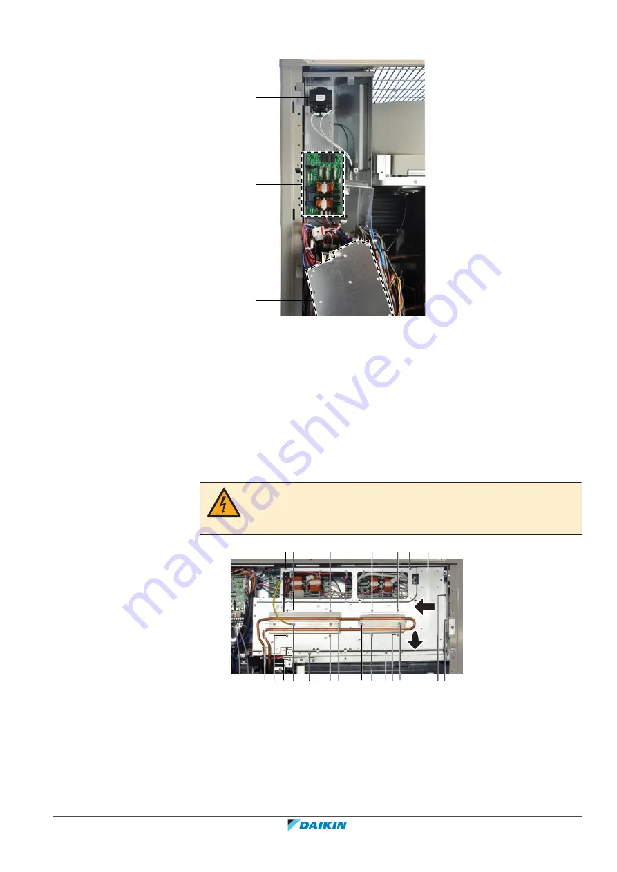
a
b
c
a
Main PCB
b
Noise filter PCB
c
Reactor
6
Completely tilt the main PCB assembly to get full access to the noise filter PCB
and the reactor.
3.15.2 To access the switch box on double fan units
Prerequisite:
Stop the unit operation via the central controller.
Prerequisite:
Turn OFF the respective circuit breaker.
1
Remove the required plate work, see
DANGER: RISK OF ELECTROCUTION
Confirm the rectifier voltage is below 10 V DC before proceeding, see
356].
b a d c e
b
a e a b
e
e
f
a
a
a
a e
e
b
a
2
1
a
Screw
b
Screw
c
Short screw
d
Screw
e
Screw
f
Inverter mounting plate
2
Do NOT loosen the screws (a) that fix the inverter PCB's at this step. These
screws need only be removed when replacing an inverter PCB.
3
Loosen and remove the 4 screws (b) that fix the heat sinks.
Summary of Contents for VRV IV+
Page 473: ......
Page 474: ......
Page 475: ......
Page 476: ...ESIE18 15B 2020 05 Copyright 2020 Daikin Verantwortung für Energie und Umwelt ...


