4
|
Third party components
Service manual
359
REYQ8~20+REMQ5U7Y1B
VRV IV+ Heat Recovery
ESIE18-15B – 2020.05
For example: if the measurements at the indoor unit side are distorted while
central controller and outdoor unit seem OK, you can suppose that the failure in
transmission is related to the indoor unit side.
7
Set time base (horizontal) to 50 µs/div to 100 µs. Voltage axis (vertical) should
be set to 2V/div to 5V. Set position properly, otherwise the data may appear
outside the screen. In AC mode, which is a sampling mode in oscilloscopes,
waveforms appear in the middle of the screen. So, it is recommended to use
AC mode if possible.
8
Set the triggering mode of the oscilloscope to "Normal". If "Auto" mode is
selected, observed waveforms may be cleared instantaneously leading to
misinterpretation of data.
9
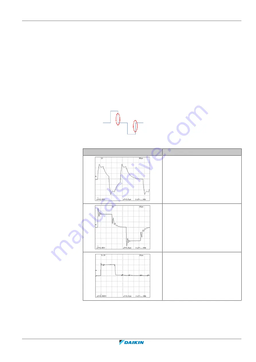
Ignore very short-time pulses of 1V amplitude or less, or overshooting at the
rising edge may be ignored. Focus on the shown points of the waveform
below:
Examples of waveform distortions on D3Net and possible causes:
Rounded waveforms at falling edges.
Possible reasons:
▪
Excessive wire length,
▪
Excessive number of connected
devices,
▪
Branching (star connections).
Ringing.
Possible reasons:
▪
Transmission wiring very close to high
voltage cables,
▪
Use of multi-conductor type wires.
Noise.
Possible reasons:
▪
Transmission wiring very close to high
voltage cables,
▪
Transmission wiring effected from
external equipment causing noise.
Summary of Contents for VRV IV+
Page 473: ......
Page 474: ......
Page 475: ......
Page 476: ...ESIE18 15B 2020 05 Copyright 2020 Daikin Verantwortung für Energie und Umwelt ...


