3
|
Components
Service manual
284
REYQ8~20+REMQ5U7Y1B
VRV IV+ Heat Recovery
ESIE18-15B – 2020.05
13
Loosen and remove the 2 screws that fix the heat pipe.
14
Loosen and remove the screw that fixes the ground wire.
15
Using a flat screwdriver, separate the heat pipe from the heat sink.
h
g
f
e
a
c
b
d
e
a
Flat screwdriver
b
Heat pipe
c
Heat sink
d
Screw
e
Power terminal assembly
f
Connector X3
g
Connector X5
h
Fan inverter PCB
16
Loosen and remove the screw that fixes the power terminal assembly.
17
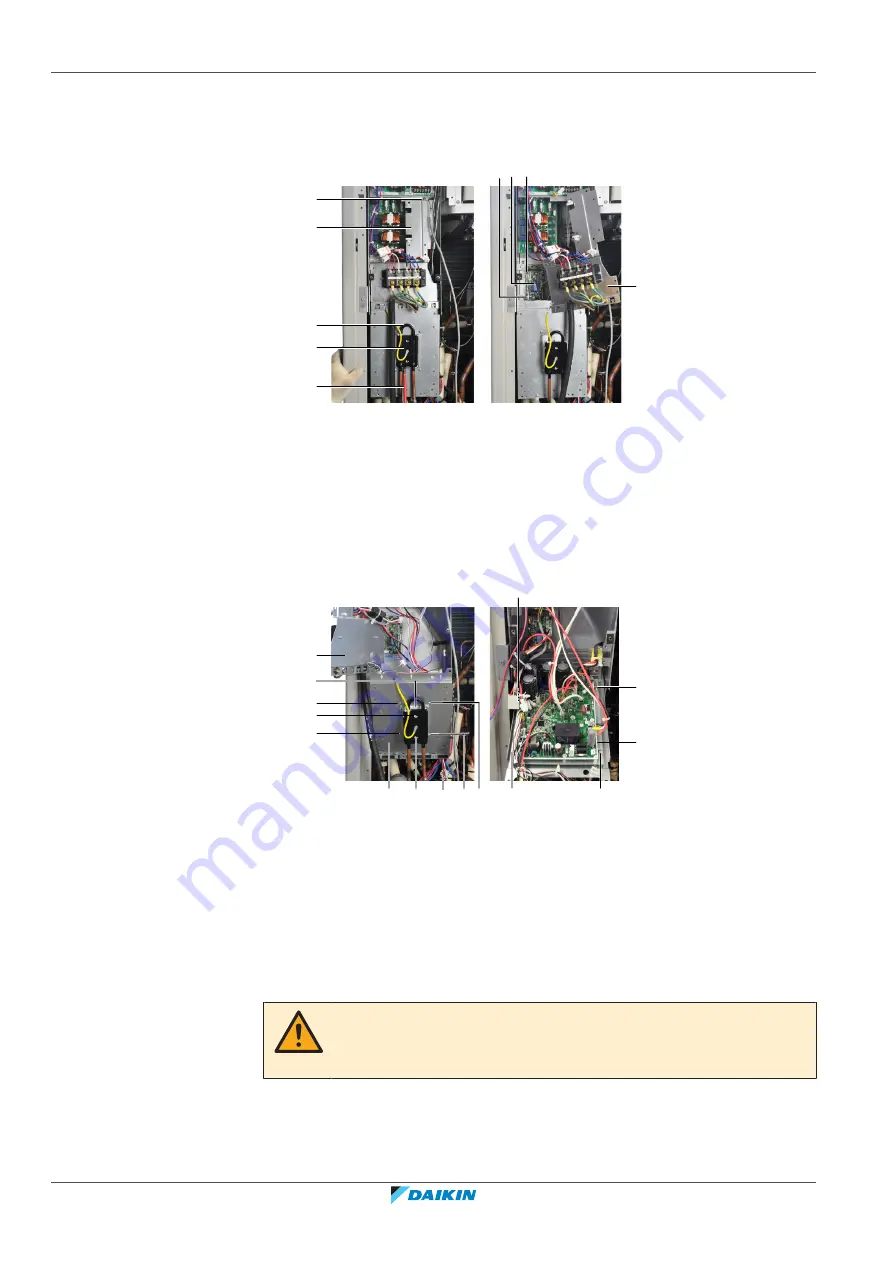
Move the power terminal assembly to the right.
f
b
f
d
a
b
b
b
c
e
d
f
f
g
g
a
Power terminal assembly
b
Screw
c
Heat sink
d
Inverter PCB
e
Compressor cable
f
Screw
g
Screw
18
Disconnect connectors X3 and X5 from the fan inverter PCB.
19
Turn the power terminal assembly to the left.
20
Remove the 4 screws that fix the heat sink.
WARNING
Thermal grease is applied to the heat sinks. Use gloves when separating the heat
sinks from the inverter boards.
21
Lift and slightly tilt the compressor inverter PCB assembly, guide the
compressor cable into the switch box.
22
Put the compressor inverter PCB assembly in horizontal position.
Summary of Contents for VRV IV+
Page 473: ......
Page 474: ......
Page 475: ......
Page 476: ...ESIE18 15B 2020 05 Copyright 2020 Daikin Verantwortung für Energie und Umwelt ...


