3
|
Components
Service manual
341
REYQ8~20+REMQ5U7Y1B
VRV IV+ Heat Recovery
ESIE18-15B – 2020.05
6
Stop the nitrogen supply when the piping has cooled down.
7
To install the solenoid valve body, see
To install the solenoid valve body
1
Install the solenoid valve body in the correct location.
2
Supply nitrogen to the refrigerant circuit. The nitrogen pressure MUST NOT
exceed 0.02 MPa.
3
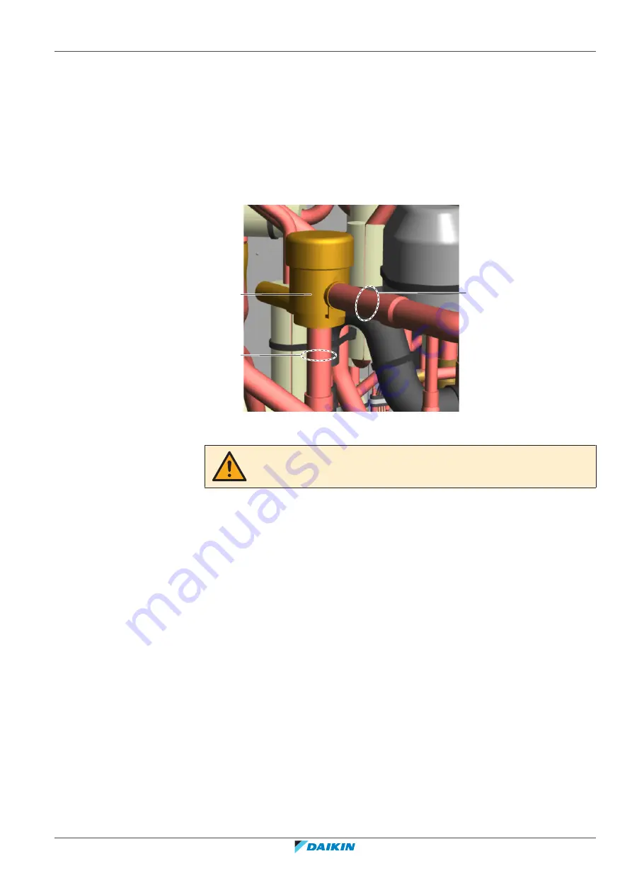
Wrap a wet rag around the solenoid valve body and solder the refrigerant
pipes to the solenoid valve body.
b
a
b
a
Solenoid valve body
b
Pipe
CAUTION
Overheating the valve will damage or destroy it.
4
After soldering is done, stop the nitrogen supply after the component has
cooled‑down.
5
To install the solenoid valve coil, see
6
Add
refrigerant
to
the
refrigerant
circuit,
see
368].
To install the solenoid valve coil
1
Install and tighten the screw to fix the solenoid valve coil to the solenoid valve
body.
Summary of Contents for VRV IV+
Page 473: ......
Page 474: ......
Page 475: ......
Page 476: ...ESIE18 15B 2020 05 Copyright 2020 Daikin Verantwortung für Energie und Umwelt ...


