3
|
Components
Service manual
277
REYQ8~20+REMQ5U7Y1B
VRV IV+ Heat Recovery
ESIE18-15B – 2020.05
a
b
a
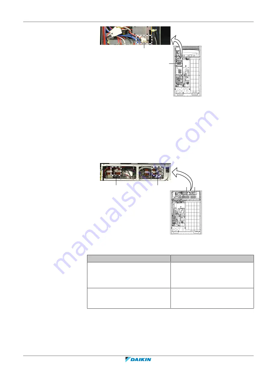
Connector X3A
b
Power terminal assembly
For double fan units
3
Measure the voltage on the rectifier voltage check connector (a) X5A to check
inverter PCB A3P (c).
Result:
The measured voltage should be approximately 560 V DC.
4
Measure the voltage on the rectifier voltage check connector (b) X6A to check
inverter PCB A6P (d).
Result:
The measured voltage should be approximately 560 V DC.
a
d
c
b
a
Connector X5A
b
Connector X6A
c
Inverter PCB A3P
d
Inverter PCB A6P
Is the measured voltage correct?
Action
Yes
Diode module and power module are
OK. Perform a power transistor check of
the inverter PCB, see
274].
No
Perform a diode module and power
module check, see
274].
To perform a diode module and power module check
Prerequisite:
First check the rectifier voltage of the inverter PCB, see
274].
Prerequisite:
Stop the unit operation via the central controller.
Prerequisite:
Turn OFF the respective circuit breaker.
Summary of Contents for VRV IV+
Page 473: ......
Page 474: ......
Page 475: ......
Page 476: ...ESIE18 15B 2020 05 Copyright 2020 Daikin Verantwortung für Energie und Umwelt ...


