6
|
Technical data
Service manual
395
REYQ8~20+REMQ5U7Y1B
VRV IV+ Heat Recovery
ESIE18-15B – 2020.05
Branch selector box BS4~16Q-A
Notes
1
This wiring diagram applies to the BS unit only.
2
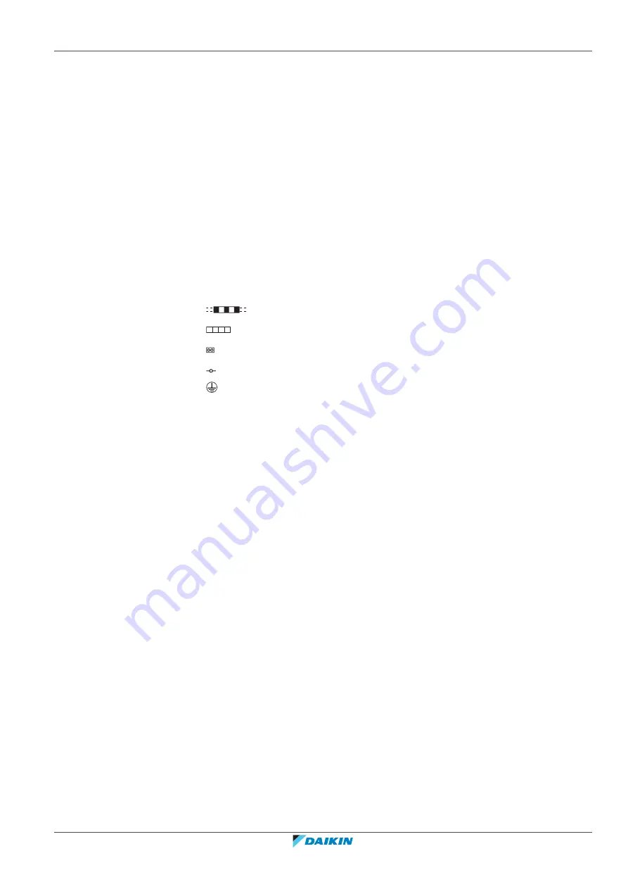
Symbols (see below).
3
For wiring for the terminal block on X2M ~ X6M (operation) , refer to the
installation manual attached to the product.
4
The factory settings of DIP switch (DS1, DS2) are as follows. For the setting
method of DIP switch (DS1, DS2), refer to ‘the installation manual’ and
‘precaution for service’ attached on the control box cover.
5
As for X15A(A1P ), remove the short circuit connector and connect the air
conditioner stop signal (optional product). For details, please refer tot he
operation manual attached to the kit.
Symbols:
Field wiring
Terminal block
Connector
Terminal
Protective earth
Legend for wiring diagram: BS4~16Q-A
A1P, A2P, A3P, A4P Printed circuit board (Control)
C1
Capacitor
DS1, DS2
DIP switch
F1U
Fuse (T 3.15 A / 250 V)
PS
Switching power supply
V1R
Diode bridge
X1M
Terminal strip (Power)
X2M, X3M, X4M,
X5M, X6M
Terminal strip (Transmission)
Z1F
Noise filter
Y1E, Y4E , Y7E,
Y10E, Y13E, Y16E,
Y19E, Y22E, Y25E,
Y28E, Y31E, Y34E,
Y37E, Y40E, Y43E ,
Y46E
Electric expansion valve (Suction)
Y2E, Y5E, Y8E,
Y11E, Y14E, Y17E,
Y20E, Y23E, Y26E,
Y29E, Y32E, Y35E,
Y38E, Y41E, Y44E,
Y47E
Electric expansion valve (HP/LP Gas)
Summary of Contents for VRV IV+
Page 473: ......
Page 474: ......
Page 475: ......
Page 476: ...ESIE18 15B 2020 05 Copyright 2020 Daikin Verantwortung für Energie und Umwelt ...


