Chapter 1
:
System Overview
2
SE500
ULTRA
Hardware Manual
SE500
ULTRA
The SE500
ULTRA
is an inline Solder Paste Inspection system that inspects solder deposits.
The SE500
ULTRA
helps to prevent production problems by notifying operators when the print
process moves outside the control tolerances. The SE500
ULTRA
is intended to help Process
Engineers to establish process tolerances.
The following pages describe the main components of the SE500
ULTRA
and show their location.
SE500
ULTRA
Unit
The SE500
ULTRA
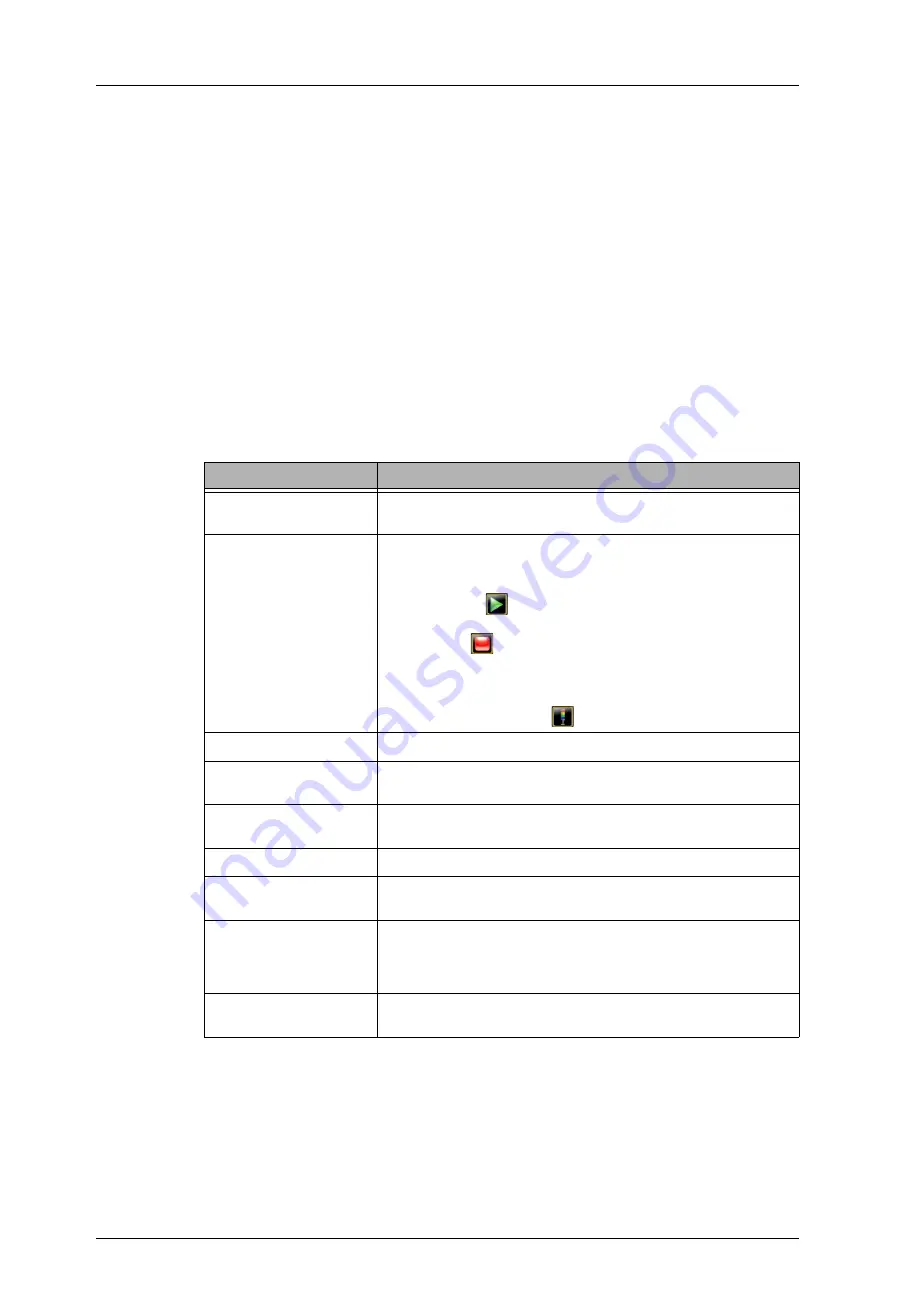
system controls and indicators are located on the outside of the unit as shown in
Figure 1 and described below.
Table 1.
SE500
ULTRA
System Components
Component
Description
Air Pressure Gauge
The LED gauge, located near the control button panel on the outer
frame of the system, displays the air pressure.
Control Buttons
The buttons on the front panel control system operation as follows:
●
E-Stop
: Stops all of the system’s moving parts.
●
Green Start
: Starts the inspection. This button is an alternative
to using the
button in the software.
●
Red Stop
: Stops the inspection. This button is an alternative to
using the
button in the software.
●
Yellow E-Stop Reset
: Initializes the system after re-engaging
the E-Stop.
●
Yellow Alarm Cancel
: Clears system alarms. This button is an
alternative to using the
button in the software.
Emergency Stop (E-Stop)
Stops all of the system’s moving parts.
ESD Grounding Plug
For connecting ESD wrist strap to prevent damage from
electrostatic discharge.
Keyboard and Trackball
Placed on a tray that is mounted on a pivoting arm attached to the
machine frame which can be folded.
Leveling Feet
Adjustable to level the unit.
Monitor
17-inch flat-panel display mounted on a pivoting arm attached to the
machine frame.
Power Switch
The power switch removes all power from the system with the
exception of the processor power. The switch can be locked in the
off position to ensure safety from moving parts while servicing the
machine.
Signal-Light Pole
Indicates the SE500
ULTRA
system status based on user
configuration.
Summary of Contents for SE500ULTRA
Page 1: ...SE500ULTRA Hardware Manual ...
Page 6: ...Contents vi SE500ULTRA Hardware Manual ...
Page 10: ...x SE500ULTRA Hardware Manual This page is intentionally left blank ...
Page 28: ...Chapter 1 System Overview 18 SE500ULTRA Hardware Manual Dimensions Figure 8 Front View ...
Page 30: ...Chapter 1 System Overview 20 SE500ULTRA Hardware Manual ...
Page 184: ...Chapter 5 System Drawings 174 CyberOptics Corporation ...


