


18
CORN I NG ASCENT FBR PD SYSTEM
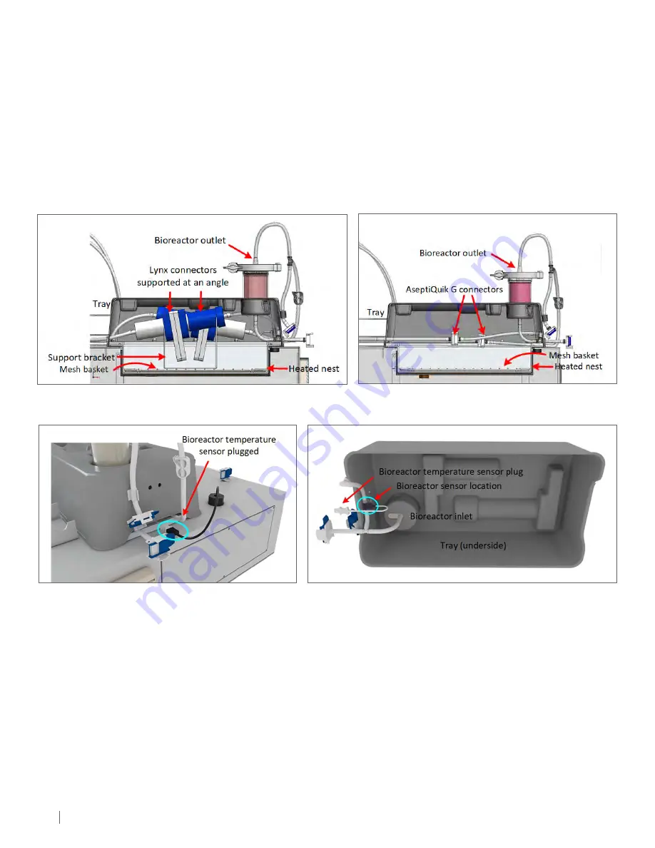
Figure 5-30.
Cross-section of the bioreactor in the tray and the
AseptiQuik® G connectors in the insulated heated nest.
5.5.2 FBR In-line Heater and Temperature Sensor
Like the MCV nest, the FBR nest is also heated. During cell culture, on consumable sets with Lynx® connectors, a supplied support bracket
positions the connectors at a 10° angle to prevent trapped air bubbles in the connectors from being transferred to the bioreactor (Figure 5-29).
On consumable sets with AseptiQuik® G connectors, the tubing and AseptiQuik® G connectors are placed on top of a mesh basket in the nest.
Both consumable sets have a mesh basket that is designed to prevent the user from having direct contact with the heated nest surface and
should be kept in place at all times when the system is in use.
The bioreactor is placed in the tray above the heated nest, creating an insulated pocket to keep the air around the sterile connectors warm.
This configuration minimizes thermal losses in the media between the MCV and the bioreactor.
The FBR nest heater provides finer media temperature control to a predefined value before its entry into the bioreactor. The heater is
controlled by the bioreactor inlet temperature sensor (Figure 5-31 and Figure 5-32).
For safety, the maximum surface temperature of the FBR nest is controlled by an integrated, self-resetting thermostat switch set to 90°C
with the controllable range between 30°C to 40°C. The bioreactor heater is limited to 80% of the duty cycle to prevent overheating.
Figure 5-29.
Cross-section of the bioreactor in the tray and the Lynx®
connectors in the insulated heated nest.
Figure 5-31.
Illustration showing the temperature sensor plugged
in while the bioreactor is in use.
Figure 5-32.
Bioreactor temperature sensor location in the media tubing along
the tray base. The sensor monitors media temperature at the bioreactor inlet.
5.6 Bar Code Scanner
The following consumables can be scanned:
• MCV sub-assembly (Figure 5-1) which includes DO and pH sensor calibration values
• FBR sub-assembly (Figure 5-11) which includes the bioreactor size and bioreactor recirculation loop volume
A 2D bar code scanner (Figure 2-2) is used to scan the bar coded consumables. While the scanner accepts most bar codes and QR formats,
only certain Corning consumables listed below are recognized and the data automatically populates the Bar Code name field in the Bar
Code Input pop-up window (see Section: 7.11.1, Figure 7.53).
For other bar codes, the user can manually enter the item name, and Accepts or Cancels the input. Once the user Accepts the input, the
data is saved in the Batch Data File.
NOTE 1:
User has to wait at least ten seconds between accepting data from the scan and next scan. Ten seconds is the time required by
the system to update the HMI with new data from each scan.
NOTE 2:
It is not recommended that the bar code reader be disconnected when the system is powered on as the reader malfunction may
occur. Cycling system power with the reader connected should reset any associated problems.


