


GR716-DS-UM, May 2019, Version 1.29
205
www.cobham.com/gaisler
GR716
•
Pulsed once during Start Conversion phase only,
•
Pulsed once during Start Conversion phase and once during Read Result phase, or
•
Asserted at the beginning of the Start Conversion phase and de-asserted at the end of the Read
Result phase
The duration of the asserted period is programmable, in terms of system clock periods, for the Chip
Select signal when pulsed in either of two phases.
The Read/Convert signal is de-asserted during the Start Conversion phase, and asserted during the
Read Result phase. The Read/Convert output signal is programmable in terms of: Polarity. The setup
timing from Read/Convert signal being asserted till the Chip Select signal is asserted is programma-
ble, in terms of system clock periods. Note that the programming of Chip Select and Read/Convert
timing is implemented as a common parameter.
At the end of the Read Result phase, an interrupt is generated, indicating that data is ready for readout
via the AMBA APB slave interface. The status of an on-going conversion is possible to read out via
the AMBA APB slave interface. The result of a conversion is read out via the AMBA APB slave
interface. Note that this is independent of what trigger started the conversion.
An ADC conversion is non-interruptible. It is possible to perform at least 1000 conversions per sec-
ond.
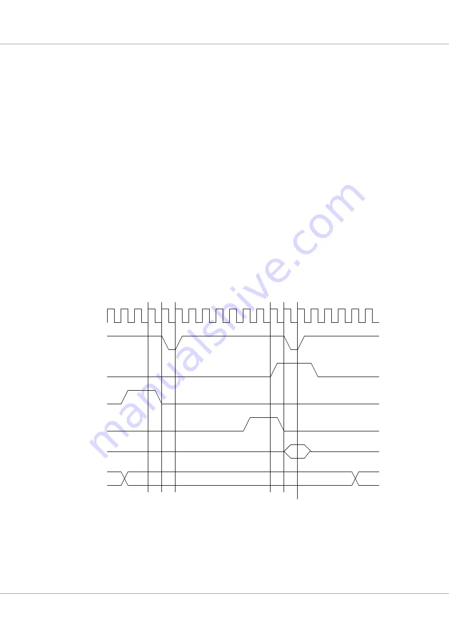
CS
RC
Trig
Rdy
Data
Addr
Clk
WS WS
Start conversion
WS WS
Read result
Sample data
Settings:
RCPOL=0
CSPOL=0
RDYPOL=1
TRIGPOL=1
RDYMODE=1
CSMODE=00
ADCWS=0
Figure 34.
Analogue to digital conversion waveform, 0 wait states (WS)


