9-2
Cisco BPX 8600 Series Installation and Configuration
Release 9.3.30, Part Number 78-12907-01 Rev. E0, May 2005
Chapter 9 Installation in Customer Cabinet
Installing a BPX Switch, Rear Rail Setback at 30-inch
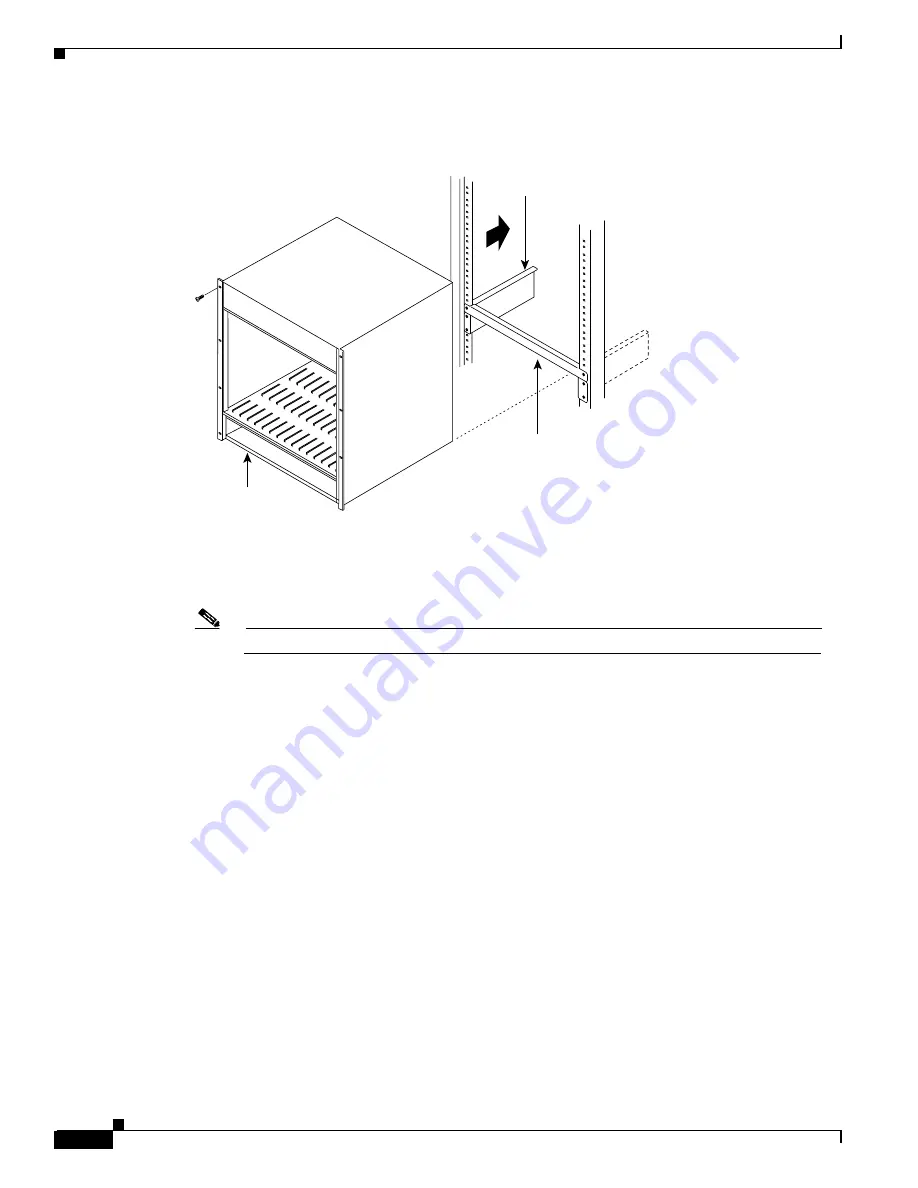
Figure 9-1
BPX Switch Aligned with Temporary Support Brackets and Spacer Bar
Step 2
Slide the BPX switch shelf into the cabinet over the temporary support bar and brackets and into place
over the flanges of the brackets previously attached to the rear rails of the cabinet.
Step 3
Secure the BPX switch shelf to the front rail using 8 each #10-32 screws.
Note
European installations may use a size M6 metric screw.
Step 4
Locate the rear support brackets (P/N 215960-00B and 215960-01B) in the miscellaneous parts kit.
Step 5
Position the adjustable plates with the tabs in the three punchouts facing up as shown in Figure 9-3.
Step 6
Align the top and bottom holes in the adjustable plates with corresponding holes in the side panel of the
BPX switch shelf. (The bottom of the plates should be approximately aligned with the bottom of a
DC- powered BPX switch shelf. They should be extended below the bottom of an AC-powered BPX
switch shelf so that the AC Power Supplies can be secured to the shelf.)
Step 7
Secure one each adjustable plate to each side of the BPX switch shelf, using (2) each #10-32 machine
screws and flat washers.
Step 8
Attach a rear support bracket to each one of the adjustable plates with 2 each #10-32 screws and washers.
Do not tighten yet.
Step 9
Secure the support brackets to the rear located vertical rails using 2 each #10-32 screws. You might have
to lift the BPX switch shelf slightly to align the holes in the bracket to the holes in the rack.
Step 10
Tighten the screws attaching the support bracket to the adjustable plate.
Step 11
Slide a cable strap over each of the three tabs on the support brackets.
Step 12
Remove the temporary support bracket and spacer bracket from the front of the cabinet.
14170
Temporary
spacer bar
BPX shelf
Temporary
support
bracket
Summary of Contents for BPX 8650
Page 49: ...P A R T 1 The BPX Switch ...
Page 50: ......
Page 159: ...P A R T 2 Installation ...
Page 160: ......
Page 273: ...P A R T 3 Initial Configuration and Network Management ...
Page 274: ......
Page 311: ...P A R T 4 Configuring Connections ...
Page 312: ......
Page 487: ...P A R T 5 Troubleshooting and Maintenance ...
Page 488: ......
Page 533: ...P A R T 6 BPX Specifications ...
Page 534: ......
Page 555: ...P A R T 7 Appendices ...
Page 556: ......


