8-10
Cisco BPX 8600 Series Installation and Configuration
Release 9.3.30, Part Number 78-12907-01 Rev. E0, May 2005
Chapter 8 Installation with Cisco Cabinets including 7000 Series Routers
Installing a 7200 or 7500 Router in a BPX 8650 Cabinet or Rack
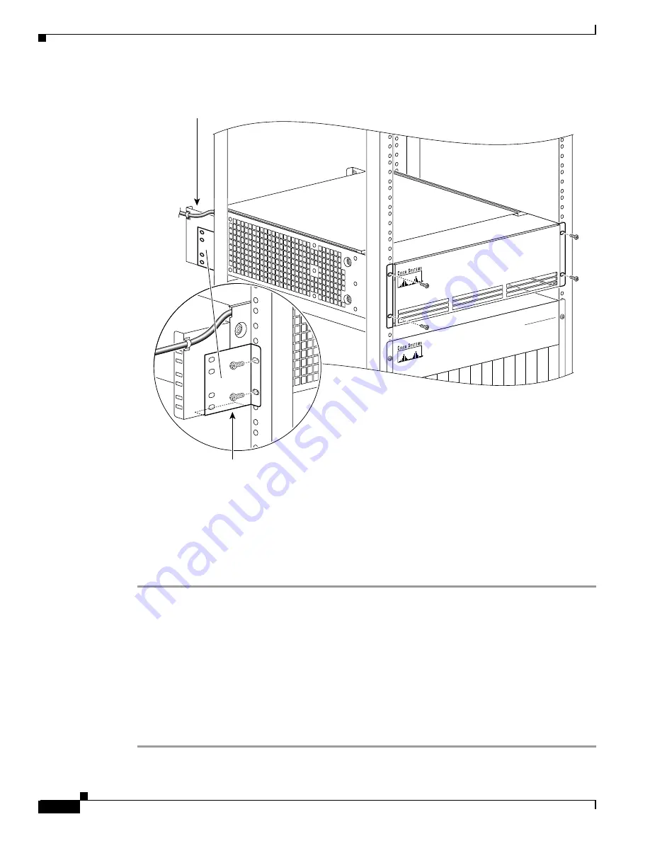
Figure 8-7
Installing the Router Enclosure Assembly in the Cisco BPX 7650 Cabinet
Installing Router Assembly in a 19-Inch Open Rack
To install the router enclosure assembly in BPX 8650 cabinet (see Figure 8-8), use the following
procedure:
Step 1
Slide the router enclosure assembly into the cabinet on top of the BPX shelf.
Step 2
Attach the two support brackets (for 19-inch open rack mounting) from the hardware kit, one to each
side of the router enclosure assembly, using two securing screws for each bracket.
Step 3
Secure the front of the router assembly to rack with two screws on each side.
Step 4
Connect the power cord to the router connector receptacle at the front of the cabinet, and close the router
enclosure assembly door.
Step 5
Use the tie wraps provided in the hardware kit to secure power cord to a Cable Management Bracket.
Step 6
If this is a DC-powered shelf, proceed to Chapter 10, “Installing the DC Shelf.”
Step 7
If this is an AC-powered shelf, proceed to Chapter 11, “Installing the AC Shelf.”
Label Switch Controler
CISCO BPX 8600
SERI
ES
W I D
E A
R E A
S W
I T C
H
19 in. cabinet
Support bracket
with lip
18722
Cable management bracket
Summary of Contents for BPX 8650
Page 49: ...P A R T 1 The BPX Switch ...
Page 50: ......
Page 159: ...P A R T 2 Installation ...
Page 160: ......
Page 273: ...P A R T 3 Initial Configuration and Network Management ...
Page 274: ......
Page 311: ...P A R T 4 Configuring Connections ...
Page 312: ......
Page 487: ...P A R T 5 Troubleshooting and Maintenance ...
Page 488: ......
Page 533: ...P A R T 6 BPX Specifications ...
Page 534: ......
Page 555: ...P A R T 7 Appendices ...
Page 556: ......


