CALREC
Putting Sound in the Picture
91
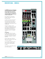
The dedicated monitor panel on the
control surface provides access
to the commonly used monitoring
controls. Access to the full set of
monitor controls can be gained from
any fader panel / up-stand TFT screen
combination by selecting Monitor
mode.
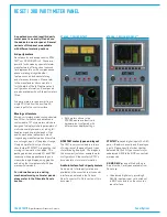
The following page shows the assignable
area of a fader panel / up-stand TFT
combination in Monitor mode with
important areas highlighted.
Assignable area mode selection is chosen
from the row of controls above the fader
label displays. Use the down arrow
buttons above the displays to select the
desired mode. If the expected mode is
not displaying, the panel is more than
likely in Tools, or Layer Tools mode - Press
Exit, or the Tools / Layer Tools button
from the bottom right of the assignable
area to return to the chosen mode.
Ensure the panel is controlling the
required output - Monitor 1 or Monitor 2
(control cell highlighted on the following
page).
Four pre-selectors determine the audio
being monitored. Switch between the pre-
selector sources by pressing the 'Hear'
buttons. To select a different source on a
pre-selector, press its' 'Sel' button to make
it the focus of the selector panel on the
TFT screen above. Selectable sources
are separated into categories, chosen
from the 'Selector Type' menu at the
bottom of the TFT screen.
A control cell on the dedicated monitor
panel, to the left of the large yellow level
control, shows the sources on each pre-
selector and allows for switching between
them without accessing the full monitor
panel.
MONITOR / METER SOURCE SELECTION
In the full monitor panel mode, to the left
of the 4 monitor pre-selectors are the
4 meter selectors. Press 'Sel' on the
appropriate meter selector to change the
source in the same way as for the monitor
selectors.
To the left of the Main monitor LS level
control, on both the dedicated and full
monitor panel is a Small LS control cell.
By default, the Small LS outputs PFL
audio. If Small LS C/O (Change-over) is
selected, it will kill the main monitor output
and instead send the selected audio to the
small LS outputs, irrespective of whether
the small LS is patched to physical output
ports / speakers.
Another control cell sets the listening level
of PFL and AFL audio.
Individual LS channel cuts provide a
convenient way to check patching and
connectivity.
Summary of Contents for Artemis
Page 5: ...calrec com Putting Sound in the Picture ARTEMIS INFORMATION...
Page 9: ...calrec com Putting Sound in the Picture ARTEMIS CONTROL SURFACE...
Page 26: ...26 ARTEMIS Digital Broadcast Production Console...
Page 27: ...calrec com Putting Sound in the Picture ARTEMIS PROCESSING CORE BEAM SHINE...
Page 33: ...calrec com Putting Sound in the Picture ARTEMIS PROCESSING CORE LIGHT...
Page 40: ...40 ARTEMIS Digital Broadcast Production Console...
Page 41: ...calrec com Putting Sound in the Picture ARTEMIS CONNECTION INFORMATION...
Page 66: ...66 ARTEMIS Digital Broadcast Production Console...
Page 67: ...calrec com Putting Sound in the Picture ARTEMIS EXTERNAL CONTROL...
Page 80: ...80 ARTEMIS Digital Broadcast Production Console...
Page 81: ...calrec com Putting Sound in the Picture ARTEMIS SETUP CONFIGURATION...
Page 100: ...100 ARTEMIS Digital Broadcast Production Console...
Page 101: ...calrec com Putting Sound in the Picture ARTEMIS PANEL OPTIONS...
Page 110: ...110 ARTEMIS Digital Broadcast Production Console...
Page 111: ...calrec com Putting Sound in the Picture ARTEMIS OBSOLETE PANELS...
Page 114: ...114 ARTEMIS Digital Broadcast Production Console...
Page 115: ...calrec com Putting Sound in the Picture ARTEMIS SPECIFICATIONS...


