108 ARTEMIS
Digital Broadcast Production Console
Panel Options
LOUDSPEAKER PANEL - LS5958
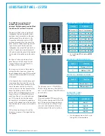
The LS5958 is an optional loud
speaker panel for the Artemis
upstand. Multiple panels can be fitted
in each control surface if required.
The panel is fitted with a single (mono)
loudspeaker, fed by 4 balanced stereo
analogue inputs, accessible on the rear
interface panel (pin-outs shown in the
Connection Information section). DIP
switches accessible from the rear of the
panel enable or disable each leg of each
input. From each of the 4 inputs, the
loudspeaker can output left, right, both or
neither. If inputs are wired but unused /
left unterminated, they should be disabled
to eliminate noise picked up by the cable
run.
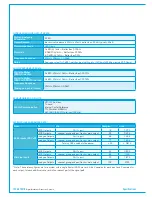
Each pair of stereo inputs has a front
panel level control, the range of which
is set by DIP switch to be either
∞
to
+10dB, or -20 to +10dB.
Each level control knob is illuminated to
aid identification, the colour of each can
be set independently using PCB mounted
rotary switches, accessible from the rear
of the panel.
A front panel button, located above each
level control functions as a Cut or an On
switch. DIP switches accessible from the
rear of the panel set this functionality,
which is shown in the front panel display
above the button, and also sets the
button LED to light appropriately for the
chosen function. Another DIP switch is
used to set the cut / on status at power
up. All four inputs can simultaneously
be remotely cut or dimmed by applying a
ground to the relevant pin on the console's
rear interface (see Connection Information
section).
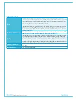
DIP switches are also used to set the
frequency response of the signal feeding
the speaker.
The flat response is +/-0.5dB 20Hz–
20KHz. A high frequency filter (4k7Hz)
and / or a low frequency filter (215Hz) can
be switched in.
Connections
This panel receives POE power from a
POE switch ancillary power (AP) or SPR
port. The audio interface and external
cut / dim lines are on a 25 pin D-type
connector wired internally to the rear
interface panel of the control surface.
CUT
CUT
CUT
CUT
SWITCH 1-4 - INPUT ENABLE/DISABLE
Input 1 Left disable
Input 1 Right disable
Input 2 Left disable
Input 2 Right disable
Input 3 Left disable
Input 3 Right disable
Input 4 Left disable
Input 4 Right disable
DIP switch 1/1
DIP switch 1/2
DIP switch 2/1
DIP switch 2/2
DIP switch 3/1
DIP switch 3/2
DIP switch 4/1
DIP switch 4/2
Switch
Function
• Set switch
on (1)
to disable,
off
(0)
to enable.
SWITCH 9/1 - BUTTON FUNCTION
Button = CUT
Button = ON
0
1
Sw 9/1
Function
SWITCH 9/2 - MINIMUM POT LEVEL
Min pot level =
∞
Min pot level = -20
0
1
Sw 9/2
Function
ROTARY SET - LEVEL
CONTROL COLOUR
Input 2
Input 1
5
6
Rotary Switch
Input knob
7
8
Input 3
Input 4
• Turn the appropriate switch to cycle
through the colours available.
Summary of Contents for Artemis
Page 5: ...calrec com Putting Sound in the Picture ARTEMIS INFORMATION...
Page 9: ...calrec com Putting Sound in the Picture ARTEMIS CONTROL SURFACE...
Page 26: ...26 ARTEMIS Digital Broadcast Production Console...
Page 27: ...calrec com Putting Sound in the Picture ARTEMIS PROCESSING CORE BEAM SHINE...
Page 33: ...calrec com Putting Sound in the Picture ARTEMIS PROCESSING CORE LIGHT...
Page 40: ...40 ARTEMIS Digital Broadcast Production Console...
Page 41: ...calrec com Putting Sound in the Picture ARTEMIS CONNECTION INFORMATION...
Page 66: ...66 ARTEMIS Digital Broadcast Production Console...
Page 67: ...calrec com Putting Sound in the Picture ARTEMIS EXTERNAL CONTROL...
Page 80: ...80 ARTEMIS Digital Broadcast Production Console...
Page 81: ...calrec com Putting Sound in the Picture ARTEMIS SETUP CONFIGURATION...
Page 100: ...100 ARTEMIS Digital Broadcast Production Console...
Page 101: ...calrec com Putting Sound in the Picture ARTEMIS PANEL OPTIONS...
Page 110: ...110 ARTEMIS Digital Broadcast Production Console...
Page 111: ...calrec com Putting Sound in the Picture ARTEMIS OBSOLETE PANELS...
Page 114: ...114 ARTEMIS Digital Broadcast Production Console...
Page 115: ...calrec com Putting Sound in the Picture ARTEMIS SPECIFICATIONS...

