54 ARTEMIS
Digital Broadcast Production Console
Connection Information
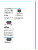
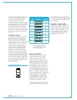
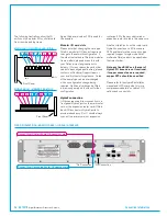
The following illustrations show the ID
switch on the modular I/O controller card
from the side and top views.
Again the decimal value of 39 is used for
the example.
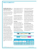
Modular I/O card slots
Please note that changing the card type
fitted in a modular I/O box slot requires a
change to the network configuration. If
the order that cards are fitted in a modular
frame matters, please discuss this with
your Calrec project engineer prior to
delivery. If for any reason the card order
needs to be changed post delivery, please
contact our Customer Support team or
your local distributor for guidance. Cards
of the same type can be interchanged
with no configuration change being
required. Additional cards can be fitted
in previously empty slots without further
configuration.
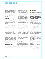
Hydra2connection
I/O boxes require a direct connection to a
front panel Hydra2 port on the main router
card, or the expansion router card if fitted.
Each I/O box has two Hydra2 ports to
provide redundancy. Port 1 should always
connect to a primary main or expansion
MODULAR I/O CONTROLLER - SIDE
0
1
2
3
4
5
6
7
ID BITS
Sw3
1
2
4
8
16
32
64
128
Front Panel
1
2 4 8 16 32 64 128
MODULAR I/O - VIEWED FROM TOP
Front Panel
router, port 2 to the secondary main or
expansion router located in the same core.
Like the Hydra2 ports on the router card,
Hydra2 connections on I/O boxes are
SFPs and therefore the connection type
required (copper / single mode fibre /
multimode fibre) needs to be specified at
the time of order.
Note, any fixed RJ45's on the rear of
Hydra2 I/O boxes are not functional,
if copper connections are required,
copper SFPs should be specified
.
Please refer to the Hydra2 installation
manual and H20 user guide for more
comprehensive details on Hydra2 I/O
options and connectivity.
FIXED FORMAT (NON-MADI) HYDRA2 I/O, REAR INTERFACE
Connect from Primary Router / Expansion card
Connect from Secondary Router / Expansion card
*No Connection *No Connection
Summary of Contents for Artemis
Page 5: ...calrec com Putting Sound in the Picture ARTEMIS INFORMATION...
Page 9: ...calrec com Putting Sound in the Picture ARTEMIS CONTROL SURFACE...
Page 26: ...26 ARTEMIS Digital Broadcast Production Console...
Page 27: ...calrec com Putting Sound in the Picture ARTEMIS PROCESSING CORE BEAM SHINE...
Page 33: ...calrec com Putting Sound in the Picture ARTEMIS PROCESSING CORE LIGHT...
Page 40: ...40 ARTEMIS Digital Broadcast Production Console...
Page 41: ...calrec com Putting Sound in the Picture ARTEMIS CONNECTION INFORMATION...
Page 66: ...66 ARTEMIS Digital Broadcast Production Console...
Page 67: ...calrec com Putting Sound in the Picture ARTEMIS EXTERNAL CONTROL...
Page 80: ...80 ARTEMIS Digital Broadcast Production Console...
Page 81: ...calrec com Putting Sound in the Picture ARTEMIS SETUP CONFIGURATION...
Page 100: ...100 ARTEMIS Digital Broadcast Production Console...
Page 101: ...calrec com Putting Sound in the Picture ARTEMIS PANEL OPTIONS...
Page 110: ...110 ARTEMIS Digital Broadcast Production Console...
Page 111: ...calrec com Putting Sound in the Picture ARTEMIS OBSOLETE PANELS...
Page 114: ...114 ARTEMIS Digital Broadcast Production Console...
Page 115: ...calrec com Putting Sound in the Picture ARTEMIS SPECIFICATIONS...

