CALREC
Putting Sound in the Picture
85
SYNC SETUP
Artemis processing cores are capable
of running on their own internally
generated synchronisation clock,
however where more than one core
is networked together, it is essential
that they are all fed and locked to the
same derived sync source to ensure
clean audio and seamless system
data transmission.
Even with a single Apollo / Artemis
console, general rules of good practise
dictate that the audio console should be
locked to the same derived sync source
as the surrounding digital equipment for
clean transfer of audio between devices.
Physically, sync inputs are on BNC
connectors located across the top of
the processing core, as described in the
Connection Information section.
By default, the system will choose to
lock to its internal clock. On initial setup,
each console's external sync input priority
should be setup.
Sync input priority can be set locally on
each console's main application, or it can
be set via H20. Neither GUI has priority
over sync choice. Changes made on
either user interface are reflected by the
other.
Where standalone router cores (without
a control surface attached) are used to
expand the network, it is essential that
the same sync source(s) are connected
and selected as the other cores on the
network. Sync settings for standalone
cores can only be accessed via H20.
MainApplicationSync
Using the local user interface on each
console, sync is set from the
>System Settings>Sync
page.
To make any changes to this page, the
user must be logged in as a technician
(see overview and GUI access).
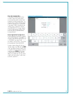
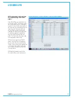
The Sync page displays the available
sync sources on the left hand side, and
the priority list on the right hand side.
The priority list displays six sources, the
last of which is fixed as internal. The first
5 sources can be selected by highlighting
the chosen source on the left, highlighting
the chosen priority list entry on the right
and clicking
patch
. When selecting a
video source, the user should also select
the specific video format being used from
the central list.
On startup, the system attempts to lock
to the first entry in the priority list. If there
is a problem with this source, the system
moves down the list until a source is
found that can be locked to. The 'current'
column shows which of the sources the
system is locked to. System Status error
messages are generated for any sources
that fail when the system attempts to
lock to them. Once running and locked,
the system will not automatically go back
to a higher priority source if it becomes
available. Clicking
Reset to first
instructs the system to go back through
the list attempting to lock to the highest
priority source it can find. This can be
an important requirement for systems
that get powered down as a whole, such
as outside broadcast units, as sync
generators can often take longer than the
console to boot up.
H20Sync
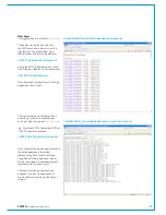
The
Sync Sources
page displays the
sync settings for all consoles and router
cores that have been added to H20's
client database. If the console being
configured does not exist in the client
list on the left of the screen it should be
added to the client database from the
Manage Clients
page (See H20 User
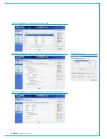
Guide for more information). On the sync
page, select any console or core from the
clients list on the left to view their sync
settings on the right. The right hand side
of the screen acts the same as the main
application, displaying the currently locked
source, allowing the sources in the sync
priority list to be changed and providing a
'reset to first' function. Changes made via
H20 are reflected in the main application
on the console they affect. Likewise, any
subsequent changes made locally will be
reflected by H20.
Summary of Contents for Artemis
Page 5: ...calrec com Putting Sound in the Picture ARTEMIS INFORMATION...
Page 9: ...calrec com Putting Sound in the Picture ARTEMIS CONTROL SURFACE...
Page 26: ...26 ARTEMIS Digital Broadcast Production Console...
Page 27: ...calrec com Putting Sound in the Picture ARTEMIS PROCESSING CORE BEAM SHINE...
Page 33: ...calrec com Putting Sound in the Picture ARTEMIS PROCESSING CORE LIGHT...
Page 40: ...40 ARTEMIS Digital Broadcast Production Console...
Page 41: ...calrec com Putting Sound in the Picture ARTEMIS CONNECTION INFORMATION...
Page 66: ...66 ARTEMIS Digital Broadcast Production Console...
Page 67: ...calrec com Putting Sound in the Picture ARTEMIS EXTERNAL CONTROL...
Page 80: ...80 ARTEMIS Digital Broadcast Production Console...
Page 81: ...calrec com Putting Sound in the Picture ARTEMIS SETUP CONFIGURATION...
Page 100: ...100 ARTEMIS Digital Broadcast Production Console...
Page 101: ...calrec com Putting Sound in the Picture ARTEMIS PANEL OPTIONS...
Page 110: ...110 ARTEMIS Digital Broadcast Production Console...
Page 111: ...calrec com Putting Sound in the Picture ARTEMIS OBSOLETE PANELS...
Page 114: ...114 ARTEMIS Digital Broadcast Production Console...
Page 115: ...calrec com Putting Sound in the Picture ARTEMIS SPECIFICATIONS...

