CALREC
Putting Sound in the Picture
51
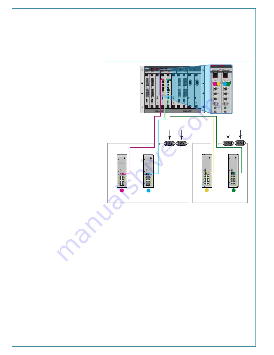
CONTROL SURFACE SIDECAR CONNECTION
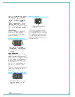
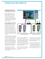
The processing core supports an
additional connection for a second
control surface known as a sidecar.
A sidecar surface, unlike a surface
extension is fitted with its own pair of
surface switches and connects to the
'Surface 2' SFP ports on the Control
Processor cards in the processing
core, as shown in the adjacent diagram.
The primary surface switch needs to be
connected to the primary controller card,
and secondary switch to secondary card
to provide redundancy.
The Calrec Main Application
>System
Settings>Surface layout
page defines
the control surface panels that are fitted.
The layout shown on the 'Surface 1'
tab relates to the main control surface,
connected to the Control Processor
'Surface 1' ports. The layout shown on
the 'Surface 2' tab relates to a sidecar
surface connected to 'Surface 2'. The
surface layout numbers the POE switches
starting from #1 for both surface 1 and
surface 2. The surface layout page allows
for different console layouts to be created,
edited, saved and loaded onto the control
surface(s).
For systems that have temporary sidecars
it is advisable to have two surface layouts
saved, one with a sidecar / surface 2 and
one without. Loading a surface layout
with a surface 2 sidecar enables the
sidecar control panels. Loading a surface
layout without a surface 2 configuration
prevents error messages being generated
for panels that are not present when the
sidecar is removed or not powered, as
well as preventing paths being placed on
faders that are not currently present.
As with the main surface, the sidecar
can be supplied with copper or fibre
connections depending on the distance
required between the processing core and
the control surface.
Both control surfaces have full access to
the DSP within the processing core as
well as to all of the I/O that the processing
core has been given access to. To prevent
control conflicts, user splits can be put
in place between the two surfaces and
different monitoring outputs can be set up
for each one. Please refer to the console
operator manual for further information on
user splits and monitoring.
Both the main surface 1, and the sidecar
surface 2 can be physically split further
using extended control surface's if
required.
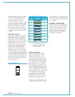
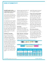
Extremely large control surface's would
require 2 pairs of surface switches fitting
in the single chassis surface in order to
be able to communicate with the high
number of control panels.
In such a case, the single chassis would
connect to both 'Surface 1' and 'Surface
2'. The surface layout for the single
control surface would be split across the
surface 1 and surface 2 screens. In such
a case, a separate sidecar cannot be
added, though surface extensions may be.
USB
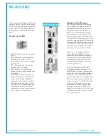
YZ5716-2
Surface Switch
IP
PS
PR
PS1
PS2
PS3
PS4
PS5
PS6
PR1
PR2
- Input Power
- POE Switch
- Power & Reset
IP2
2
4
6
1
3
5
IP1
A
B
Serial number
USB
YZ5716-2
Surface Switch
IP
PS
PR
PS1
PS2
PS3
PS4
PS5
PS6
PR1
PR2
- Input Power
- POE Switch
- Power & Reset
IP2
2
4
6
1
3
5
IP1
A
B
Serial number
Sidecar / Remote Surface
AC in
AC in
USB
YZ5716-2
Surface Switch
IP
PS
PR
PS1
PS2
PS3
PS4
PS5
PS6
PR1
PR2
- Input Power
- POE Switch
- Power & Reset
IP2
2
4
6
1
3
5
IP1
A
B
Serial number
USB
YZ5716-2
Surface Switch
IP
PS
PR
PS1
PS2
PS3
PS4
PS5
PS6
PR1
PR2
- Input Power
- POE Switch
- Power & Reset
IP2
2
4
6
1
3
5
IP1
A
B
Serial number
CONTROL
ROUTER / EXPANDER
ENABLE
DSP
SYSTEM
RESETS
FAIL
GOOD
FANS
AES 3
VIDEO 2
VIDEO 1
WORD
CLOCK
SYNC INPUTS
DSP 1
PROCESSOR 1
PROCESSOR 2
DSP 2
PSU 1
PSU 2
CONTROL
EXPANSION 1
ROUTER 1
EXPANSION 2
ROUTER 2
POK
ST0
ST1
ST2
ST3
ST4
ST5
ST6
AC IN
USB
ST1
ST2
ST3
ST4
ST5
ST6
AC IN
USB
POK
ST0
ROUTER / EXPANDER
PSU
PSU
ROUTER / EXPANDER ROUTER / EXPANDER
DSP
DSP
ROUTER / EXPANDER
POK
MA
PRI
RST
MOK
NOK
ST1
ST2
POK
MA
PRI
RST
MOK
NOK
ST1
ST2
POK
MA
PRI
RST
MOK
NOK
ST1
ST2
POK
MA
PRI
RST
MOK
NOK
ST1
ST2
POK
MA
PRI
RST
MOK
NOK
ST1
ST2
POK
MA
PRI
RST
MOK
NOK
ST1
ST2
D1
D2
D3
D4
D5
D6
D7
D8
D1
D2
D3
D4
D5
D6
D7
D8
9
11
13
15
10
12
14
16
1
3
5
7
2
4
6
8
10
9
12
11
14
13
16
15
2
1
4
3
6
5
8
7
ETHERNET
LINKS
LINKS
9
11
13
15
10
12
14
16
1
3
5
7
2
4
6
8
10
9
12
11
14
13
16
15
2
1
4
3
6
5
8
7
ETHERNET
LINKS
LINKS
9
11
13
15
10
12
14
16
1
3
5
7
2
4
6
8
10
9
12
11
14
13
16
15
2
1
4
3
6
5
8
7
ETHERNET
LINKS
LINKS
9
11
13
15
10
12
14
16
1
3
5
7
2
4
6
8
10
9
12
11
14
13
16
15
2
1
4
3
6
5
8
7
ETHERNET
LINKS
LINKS
CONTROL PROCESSOR
MAC 6
MAC
4
MAC
3
MAC
5
USB
1
MOUSE
KBD
VGA
D1
D0
R1
R0
E1
E0
MA
POK
RST
PRI
NOK
MOK
ST2
ST1
LOW BATT
CF
USB
2
MAC 7
CONTROL PROCESSOR
MAC 6
MAC
4
MAC
3
MAC
5
USB
1
MOUSE
KBD
VGA
D1
D0
R1
R0
E1
E0
MA
POK
RST
PRI
NOK
MOK
ST2
ST1
LOW BATT
CF
USB
2
MAC 7
A
A
A
A
Primary
Secondary
Primary
Secondary
Main Control Surface
1
2
3
4
1
3
4
2
MAIN SURFACE / SURFACE 1 & SIDECAR / SURFACE 2 CONNECTIONS
Summary of Contents for Artemis
Page 5: ...calrec com Putting Sound in the Picture ARTEMIS INFORMATION...
Page 9: ...calrec com Putting Sound in the Picture ARTEMIS CONTROL SURFACE...
Page 26: ...26 ARTEMIS Digital Broadcast Production Console...
Page 27: ...calrec com Putting Sound in the Picture ARTEMIS PROCESSING CORE BEAM SHINE...
Page 33: ...calrec com Putting Sound in the Picture ARTEMIS PROCESSING CORE LIGHT...
Page 40: ...40 ARTEMIS Digital Broadcast Production Console...
Page 41: ...calrec com Putting Sound in the Picture ARTEMIS CONNECTION INFORMATION...
Page 66: ...66 ARTEMIS Digital Broadcast Production Console...
Page 67: ...calrec com Putting Sound in the Picture ARTEMIS EXTERNAL CONTROL...
Page 80: ...80 ARTEMIS Digital Broadcast Production Console...
Page 81: ...calrec com Putting Sound in the Picture ARTEMIS SETUP CONFIGURATION...
Page 100: ...100 ARTEMIS Digital Broadcast Production Console...
Page 101: ...calrec com Putting Sound in the Picture ARTEMIS PANEL OPTIONS...
Page 110: ...110 ARTEMIS Digital Broadcast Production Console...
Page 111: ...calrec com Putting Sound in the Picture ARTEMIS OBSOLETE PANELS...
Page 114: ...114 ARTEMIS Digital Broadcast Production Console...
Page 115: ...calrec com Putting Sound in the Picture ARTEMIS SPECIFICATIONS...


