CALREC
Putting Sound in the Picture
71
To enhance redundancy, and minimise
the amount of change-over required in
the event of a failure, both the primary
and secondary Calrec controller cards
can communicate over each other's front
panel ports - in the event of a primary
controller card failing, the secondary
would automatically become active, but
would still send and receive CSCP data
over the connection made to the primary
card.
Secondaryconnections
Third party CSCP controllers that support
redundant secondary connections should
be connected to one of the ethernet ports
(MAC5 port for the 8U or older 4U control
processor design) on both the primary
and secondary Calrec controller cards to
provide complete redundancy, protecting
against cable / port failure and card
removal. If required, this connection can
be via an Ethernet switch, e.g. to allow a
single RJ45 port on a 3rd party controller
to connect to both primary and secondary
Calrec ports.
Multipleconsoles
If CSCP connections from multiple Calrec
consoles are to be networked together,
the consoles need to connect via a layer3
(IP) Ethernet switch in order to prevent
MAC address conflicts.
ConnectingviacorporateLAN
DHCP servers run on the Calrec Control
Processor cards to allow easy connection
of a PC from configuration purposes
or to access H2O. The PC should be
connected to one of the Ethernet ports
on the front of the control processor (or
via the MAC5 port for the 8U or older 4U
design). If a CSCP or other connection is
to be made to these ports via a corporate
LAN, it is important that the Calrec DHCP
servers are disabled and the connections
are manually configured as appropriate.
Configuration
Please discuss your installation
requirements with your Calrec sales
representative or distributor prior to
delivery. CSCP connections should be
configured and tested by, or under the
guidance of a Calrec approved engineer.
The following points should be noted
when communicating your requirements:
The default Calrec IP addresses are xxx.
yyy.1.0 for the primary, and xxx.yyy.2.0
for the secondary Control Processor
cards. xxx.yyy is unique for each Apollo /
Artemis / Standalone Router processing
core and can be confirmed by running
the Program Updater GUI. If the default
addresses are not suitable, please supply
alternative IP addresses and a subnet
mask which can be configured pre-
delivery or during commissioning.
If required, the Calrec system can be
configured to connect via an IP gateway.
In addition to connecting by IP address,
both the Calrec system and the 3rd party
require configuring to use the same TCP
socket port.
The default TCP socket
port for CSCP is 49200
.
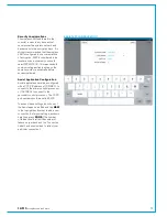
User&bootupenable/disable
Once configured, CSCP can be enabled
or disabled from the console's Main
Application,
>System Settings>Ext Control
screen.
Being part of the System Settings,
the enabled / disabled selection is
automatically saved for recall after a reset
or power cycle. System settings are not
saved as part of the show or user memory
and will therefore not change when
different shows / memories are loaded
onto the control surface.
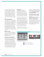
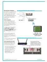
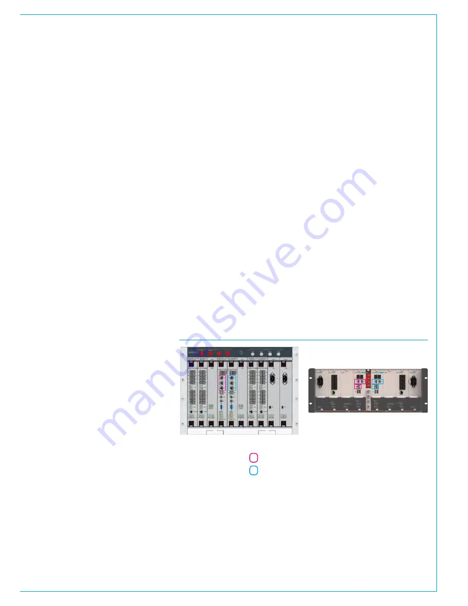
PORTS AVAILABLE FOR CSCP CONNECTIONS
• Standard 8U processing core
• 4U Artemis Light core
Primary Calrec controller ports
Secondary Calrec controller ports
Summary of Contents for Artemis
Page 5: ...calrec com Putting Sound in the Picture ARTEMIS INFORMATION...
Page 9: ...calrec com Putting Sound in the Picture ARTEMIS CONTROL SURFACE...
Page 26: ...26 ARTEMIS Digital Broadcast Production Console...
Page 27: ...calrec com Putting Sound in the Picture ARTEMIS PROCESSING CORE BEAM SHINE...
Page 33: ...calrec com Putting Sound in the Picture ARTEMIS PROCESSING CORE LIGHT...
Page 40: ...40 ARTEMIS Digital Broadcast Production Console...
Page 41: ...calrec com Putting Sound in the Picture ARTEMIS CONNECTION INFORMATION...
Page 66: ...66 ARTEMIS Digital Broadcast Production Console...
Page 67: ...calrec com Putting Sound in the Picture ARTEMIS EXTERNAL CONTROL...
Page 80: ...80 ARTEMIS Digital Broadcast Production Console...
Page 81: ...calrec com Putting Sound in the Picture ARTEMIS SETUP CONFIGURATION...
Page 100: ...100 ARTEMIS Digital Broadcast Production Console...
Page 101: ...calrec com Putting Sound in the Picture ARTEMIS PANEL OPTIONS...
Page 110: ...110 ARTEMIS Digital Broadcast Production Console...
Page 111: ...calrec com Putting Sound in the Picture ARTEMIS OBSOLETE PANELS...
Page 114: ...114 ARTEMIS Digital Broadcast Production Console...
Page 115: ...calrec com Putting Sound in the Picture ARTEMIS SPECIFICATIONS...


