CALREC
Putting Sound in the Picture
19
SurfaceSwitches
The Surface Switch is the interface
between the control surface and the
processing core. To provide redundancy,
two Surface switches are fitted, primary
and secondary. The system will always
attempt to boot and run on the primary,
however if there is a problem with the
primary or its connections, the secondary
will automatically take over.
Like POE's, the Surface Switches are
mounted to the inside of the rear cover,
usually in the same section as the IEC
inlets. Access is gained by removing
control panels or the rear cover as shown
in the surface dimensions section of this
document. When viewed from the front,
the primary Surface Switch is always the
left hand unit. See Figure 5.
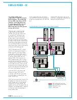
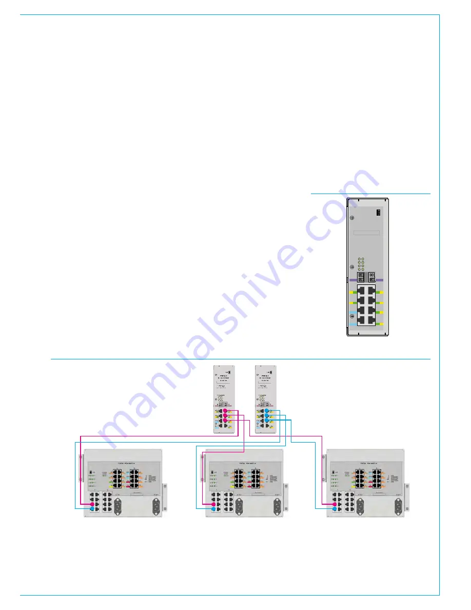
To communicate with all the control panels
and PC, each Surface Switch requires a
direct connection to each POE switch.
POE switches MUST be connected to
specific ports in the correct order:
POE #1 connects to surface switch port
PS1, POE#2 to PS2, POE #3 to PS3 etc.
POE's are numbered by location from
left to right across the console. Figure 6
shows the correct data connections for a
3 x POE system. On each POE, port S1
connects to the primary Surface switch,
port S2 to the secondary. LEDs 1 - 6
show activity on these ports and should
display a regular flashing pattern once
booted and comms established. Although
the POE sends power down these lines,
the Surface Switches do not use it.
Any POE SPR ports can be used to feed
Surface Switch PR1/PR2 ports to power
the Surface Switch as well as passing on
the reset signals. LEDs I/P1 and I/P2
indicate if power is present on these ports.
Ports A & B are SFP slots Port A is used
to interface with the Control Processor
in the processing core, port B is currently
unused. The primary Surface Switch
should connect to the primary Control
Processor's 'Surface 1' connector (MAC7
for the 8U or older 4U Control Processor
design) . The secondary Surface
Switch should connect to 'Surface 1'
on the secondary Control Processor.
These connections are NOT supplied
by Calrec and need to be made by the
installer. Please see the Surface to Core
Connection section of this document for
more details.
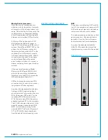
USB
YZ5716-2
Surface Switch
IP
PS
PR
PS1
PS2
PS3
PS4
PS5
PS6
PR1
PR2
- Input Power
- POE Switch
- Power & Reset
IP2
2
4
6
1
3
5
IP1
A
B
Serial number
FIGURE 5 - SURFACE SWITCH
Primary
Surface
Switch
Secondary
Surface
Switch
POE #1
POE #2
POE #3
FIGURE 6 - POE TO SURFACE SWITCH DATA CONNECTIONS
Summary of Contents for Artemis
Page 5: ...calrec com Putting Sound in the Picture ARTEMIS INFORMATION...
Page 9: ...calrec com Putting Sound in the Picture ARTEMIS CONTROL SURFACE...
Page 26: ...26 ARTEMIS Digital Broadcast Production Console...
Page 27: ...calrec com Putting Sound in the Picture ARTEMIS PROCESSING CORE BEAM SHINE...
Page 33: ...calrec com Putting Sound in the Picture ARTEMIS PROCESSING CORE LIGHT...
Page 40: ...40 ARTEMIS Digital Broadcast Production Console...
Page 41: ...calrec com Putting Sound in the Picture ARTEMIS CONNECTION INFORMATION...
Page 66: ...66 ARTEMIS Digital Broadcast Production Console...
Page 67: ...calrec com Putting Sound in the Picture ARTEMIS EXTERNAL CONTROL...
Page 80: ...80 ARTEMIS Digital Broadcast Production Console...
Page 81: ...calrec com Putting Sound in the Picture ARTEMIS SETUP CONFIGURATION...
Page 100: ...100 ARTEMIS Digital Broadcast Production Console...
Page 101: ...calrec com Putting Sound in the Picture ARTEMIS PANEL OPTIONS...
Page 110: ...110 ARTEMIS Digital Broadcast Production Console...
Page 111: ...calrec com Putting Sound in the Picture ARTEMIS OBSOLETE PANELS...
Page 114: ...114 ARTEMIS Digital Broadcast Production Console...
Page 115: ...calrec com Putting Sound in the Picture ARTEMIS SPECIFICATIONS...


